Upgrading an LC Meter Kit: A DIY Enhancement Project
Upgrade Your Budget LC Meter Kit: A DIY Enhancement Project The HU-053 LC Meter kit is a budget-friendly option for measuring capacitance, inductance, and frequency, available online. With its easy-to-solder components and transparent acrylic enclosure, it’s a great weekend project for electronics enthusiasts. But how accurate is it, and can we make it better? Kit Contents and Assembly The HU-053 kit includes a double-sided PCB, a bag of components, a transparent acrylic enclosure, and all the necessary nuts and bolts for assembly. The assembled device measures 91 × 106 mm with a height of 28 mm, featuring an alphanumeric LCD, a 40-pin STC89C52RC microcontroller, a 3P4T function selection switch, and a ZIF socket for connecting the component to be tested. The unit is powered by a 5-V supply. Improving the LC Meter’s Accuracy After assembling and testing the device, we were disappointed to find that its accuracy was as low as its price. But this presented an opportunity to improve it! In this article, we’ll explore ways to enhance the HU-053 LC Meter’s performance, making it a more reliable measurement instrument. Download the article to learn how to upgrade your budget LC Meter kit and turn it into a useful tool for your electronics projects.
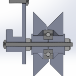
Ultimaker2 Bearing Spool and Bearing Guide Upgrade
This is an upgrade to the Ultimaker2 3D printer for people who have spools that do not fit the original spool holder, and spools that are too tight and thus do not feed smoothly, causing under-extrusion. It is composed of two assemblies: a replacement for the filament guide and a replacement for the spool holder. Both utilizes ordinary skateboard bearings to achieve smooth rotation. The conical shape of the spool holder allows for any sized spool to be used, easily swapped because it uses a wing nut. Files are available on YouMagine. I want to emphasize that I am sharing the STEP files, not just STL, because STL are harder for people to import and modify than STEP files. SolidWorks files are also provided. The cross section images shows you how to assemble the upgrade parts. The screw diameters are #6 for the filament guide and 5/16″ for the spool holder. Please figure everything else out from the cross section images.
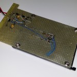
3D Printed Battery Recharge Dock for Parrot Rolling Spider
I got a Parrot Rolling Spider for fun. The batteries are 570mAH and the life is under 10 minutes, plus the reviews often mention that the batteries will lose their capacity quickly. Further research into this problem indicated that charging them slowly will alleviate this problem. I wanted a few spare batteries and a way to recharge them. I decided to DIY a dock for them. I had a handful of spare parts, such as the MCP73831 and plenty of small perfboards. All I needed to do was 3D print something to hold the batteries in place, and this is what I came up with. More pictures if you continue reading. The red LED is always on as long as there is power. When a battery is done recharging, a green LED will turn on. The MCP73831 are configured to charge at a slow 200mA each, totalling 400mA, which is under the 500mA limit for low power USB ports. Sure… I could’ve probably fit 6 batteries onto one board, standing vertically. But I didn’t want to actually buy 6 batteries for a toy. Sorry, no circuit diagram was drawn prior to the rapid prototype, but it’s nearly identical to the example circuit inside the MCP73812 datasheet. The battery connector is a 2199011-1 from TE Connectivity, or A120576 on Digi-Key. The design is shared on Onshape, click here. Print at around 27% infill and 1.2mm wall thickness. The…
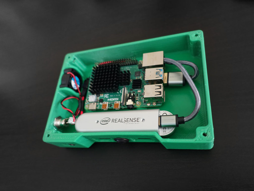
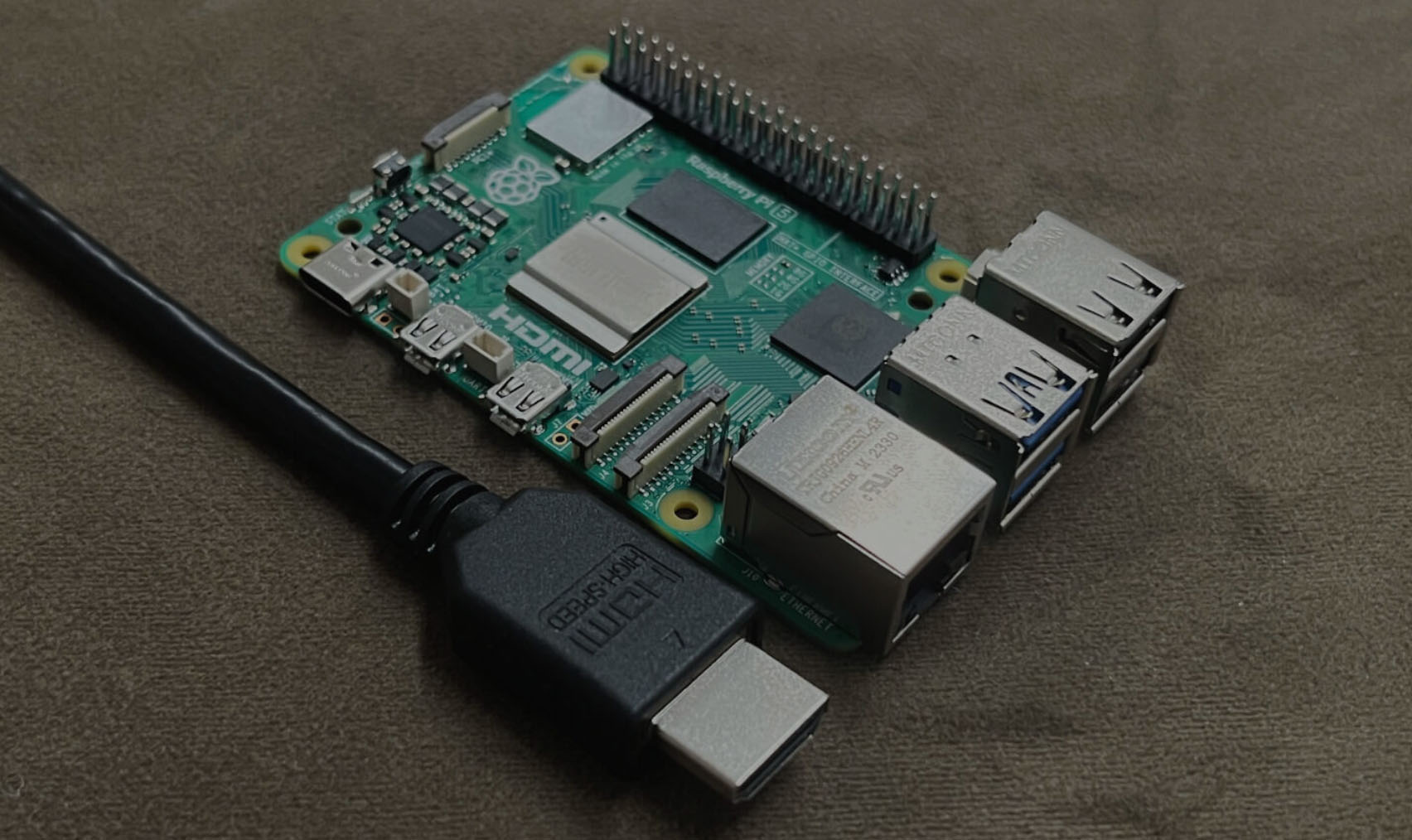
Handheld 3D Scanner: Based on Raspberry Pi
I’ve had some fun with photogrammetry recently and wanted to try out other techniques for 3D scanning. I’ve actually sort of accomplished S.L.A.M. during a hackathon using the PlayStation 4 camera and the Xbox One Kinect already, but I wanted something portable! With the new Raspberry Pi 4 debuting this year, I can finally accomplish this… sort of… Inside this 3D printed case is a Raspberry Pi 4 and a Intel RealSense D415 camera. The D415 is a depth sensing camera, using active stereo IR cameras and an internal processor to generate depth map data. It also has an ordinary RGB camera as well. That’s a lot of data to push through, hence why the newest Raspberry Pi 4 this year is important, because it has USB 3.0 ports that can handle all that data. (the ARM processor inside also has a faster architecture than before) How does the depth sensing work? Have you read my post on photogrammetry yet? There are some overlaps between the techniques. There are two IR cameras spaced apart, and it can see two very similar but shifted images. The processor finds interesting points (i.e. feature extraction) in the two images that are similar and match them up, the coordinates of these points can be used to calculate the 3D coordinates of those points relative to the cameras (i.e. binocular disparity). Why infrared? When there are not a lot of interesting features for the processor to look at, the…

Guiding Students to Master Robotics Technology
I spend my Saturdays volunteering at a public library makerspace, the South San Francisco Public Library. I help people operate a few 3D printers, a CNC mill, vinyl cutter, etc. While preparing for my annual RoboGames entry, I thought it’d be cool to teach the library’s patrons about robotics. I designed a robot kit, partly 3D printed, with electronics that has to be soldered, and running with an Arduino Nano. The three classes are for 3D CAD modelling, soldering, and programming. The robots are designed to be cheap enough for the library to actually give away. All of my courseware is open source, hosted on GitHub. A lot of the tools and parts were donated by people I know in my professional circles. Here’s a link to the class content: click here This blog post is about what I observed, what I did right, what I did wrong. Day 1 – July 7 2018 Today is the 3D modelling class! For reference, all the class material used on this date is git hash 31871E2325BAFFEC8535DCAC8AB0131F2227401C. Use this to see what improvements were made to the class content after this date. Click Here to see this particular lesson’s page. Promotion, Registration, and Attendance The advertising is mainly from a video on the library’s events page. (this was done for me by library staff, the video is shown above if you want to see it) Class size has to be limited to 10.…
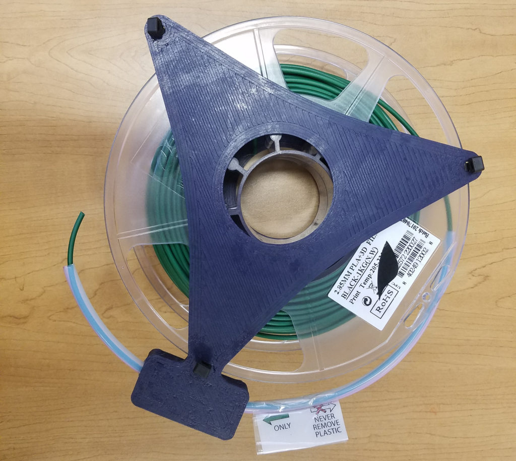
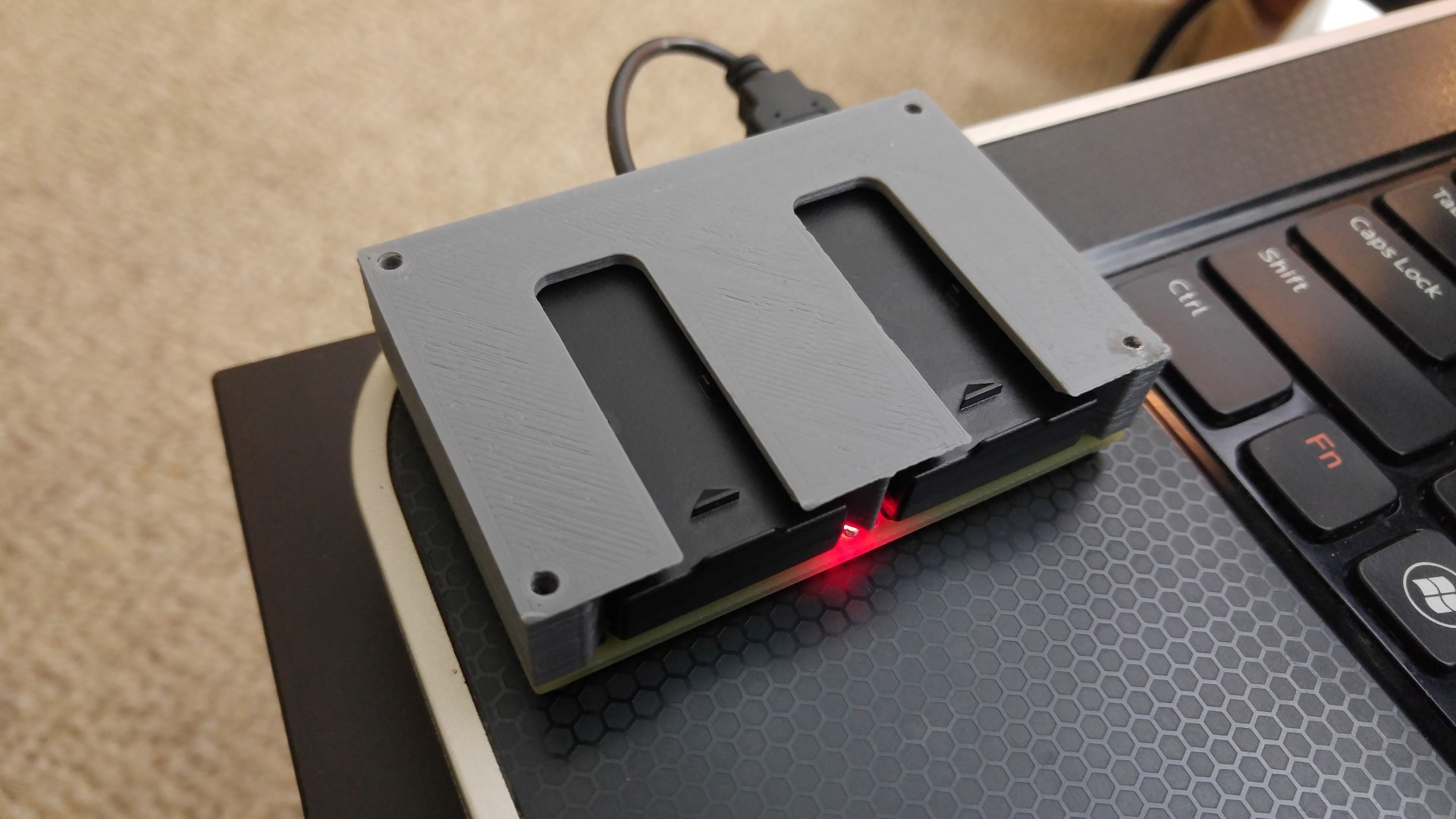
Upgrading Public Library 3D Printers to Ink-Based Printing Systems
Ha, that title makes me sound so evil. See… this library actually leaves their 3D printers unsupervised, and the patrons use them how they please. I love it, getting people exposed to the latest tech is our goal. But this means that people do not realize how to properly remove filament from the printers, leading to tangles and knots in the filament spools. A single mistake could essentially render a $20 spool useless, it becomes a time bomb for printer jams, making people unhappy. No amount of posters or instructions booklets could embed the same kind of discipline that a 3D printer owner has regarding filament treatment. Just a simple mistake of letting the filament go could cause a knot in the spool. My solution… make them use cartridges that make it hard to make mistakes. These cartridges must be cheap, fast to make, easy to understand, reusable, and do not require modifying the printer to use. Don’t worry, there’s no DRM bull**** and they are adjustable to fit any standard spools. If my idea causes more problems than it solves, simply clip all the zip ties and go back to status-quo. It’s just two plates, sandwiching a spool, with 3 zip ties to make sure the spool doesn’t fall out but still allow the spool to spin. The magic is the teflon tube that’s attached to one of the plates … … which serves the…
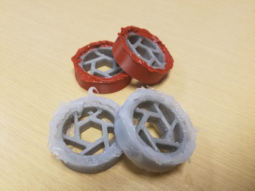
Manufacturing 3D Printed Molds for Small Robot Wheels
For my antweight combat robot DetCord, I wanted a wheel that could improve upon the Banebots wheels that I used before. I wanted something shock absorbing, which would extend the life of my gearboxes. The tires need to be soft and have high traction. The wheel does not have to be very strong because the robot has thick armour to protect the wheels. I ended up with a cool way to make a wheel that’s cleaner than the more popular methods I see on the internet! I can print the wheel hub in TPU with spiralling spokes for shock absorbtion. But 3D printed TPU is shore 95A and so doesn’t grip as well as the shore 30A Banebot wheels I already have. I need a tire that’s a softer material with high traction. I researched and found plenty of resources on how to make wheel molds for liquid urethane mixtures. But searching around I can’t find liquid urethane in low quantities, and the casting process sounded like a pain. I thought this would be a good challenge, the rules are: only use materials I can 3D print easily, and a single liquid that can be purchased in low quantities and doesn’t require mixing. So I ended up choosing TPU for the wheel hub, PVA for the tire mold, and “liquid gasket” as the tire. My mold is printed out of PVA, it’s a water soluble plastic. So…

Design of Car Head-Up Display Using LED Strip
This is the next step in my mission to make my car function 7 years newer and feel like a jet cockpit. (click here if the above video isn’t loading) I wanted a HUD, Heads Up Display to my car. The main purpose is to let me keep my eyes on the road and still be aware of my speed without looking down, hence “heads up”. This idea has been used in fighter jets for decades now. I do not like any of the other ones on the market today, they all try to do “too much”. I wanted something more simple and elegant. My design is a simple RGB capable individually controllable LED strip that reflect off my windshield. I used the “DotStar” from Adafruit Industries, which uses APA102 LEDs. The brain is a Teensy 3.2, which is connected to my car’s CAN bus via a OBD-II connector (the diagnostic port that you can read the engine computer from). It is programmed to have three different modes: voltmeter, tachometer, and speedometer. The mode switching is “context aware”: When the car is moving, the mode changes to speedometer. If I rev the engine without the car moving, the mode changes to tachometer. When the engine is off, the voltmeter shows me the car’s battery voltage. When transitioning between the modes, there’s a few preset transition animations that are randomized. When the car is off, the circuit goes into sleep mode. Click play on the video below…
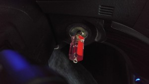
My Car Was ‘Stolen’ by Myself, What Should I!?
Yea so I had no choice but to start my car with a screwdriver (continue reading) Just kidding. This was inspired by these similar projects
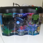
Naked HDD Activity Indicator
Remember my Aquarium Computer? I thought the SSD looked boring, so I put a old-school HDD inside with all the guts exposed, and wired it electrically to spin and swing when there is hard drive activity (when the HDD activity LED blinks). But I have a deep dark secret… OK I’ll be honest, this is a “failed” project. I considered it a failure because I got lazy and used a MTD6501 chip to spin the platter, but it always spins for a little bit and just stops. I don’t know why, I don’t see the power dipping on o’scope traces. That chip is designed for driving things like cooling fans. Another reason why I think it’s a “failed” project is because IT IS ANNOYING AS HELL BECAUSE IT IS SO GOD DAMN FUCKING LOUD. Obviously it’s because my primitive circuit is simply using a MOSFET to shoot as much current through the coil as possible, thus smashing it from end to end. A better circuit would obviously use some form of current control, and obviously a real HDD circuit would control the coil with micrometer precision. But it was still fun. I leave it disconnected. Here is the rough circuit: Yes, I understand I can make huge improvements, but I did it with spare parts in one day. Remember to check the polarity of the read head voice coil first! On a side note, if you simply power up…