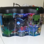
Aquarium Computer
My trusty laptop is showing its age. 8 GB of RAM is not enough for the amount of 3D stuff I do now, and it can’t run the latest games at all any more. Since I got a full time job now (instead of a constantly travelling student), it’s time to get a desktop PC (first PC build, yay). But the process of building a PC is pretty boring, it’s just an exercise of picking out compatible parts for the right price. I decided to make it slightly more interesting by submerging the entire computer in a fish tank full of mineral oil. UPDATE March 2015, I added a funny naked HDD activity indicator Some pictures from the build process Animated Loop Short Story (long story later, technical details and stuff): Intel i7 4790S, Nvidia GTX 970, H97M chipset, Corsair CX600M. Built onto a polycarbonate tray that is then dipped into a fish tank full of mineral oil. Fancy features like bubbling treasure chest, NeoPixel LED strip, oil pump+radiator, temperature monitoring, removable SSD. (part list? fine… here… these are not the prices I paid but here it is http://pcpartpicker.com/user/frank26080115/saved/HFDmP6) Comments and questions are welcome, I would love to chat with you! Reddit posts, please upvote: http://www.reddit.com/r/battlestations/comments/2pdd3q/aquarium_computer_mineral_oil_submerged_details/ and http://www.reddit.com/r/buildapc/comments/2pdeak/build_complete_aquarium_computer_mineral_oil/ Hi Hack a Day visitors, small correction: there’s 32 GB of RAM, I just didn’t put the same item twice in the part list. News/Updates will be posted at the bottom of this page…
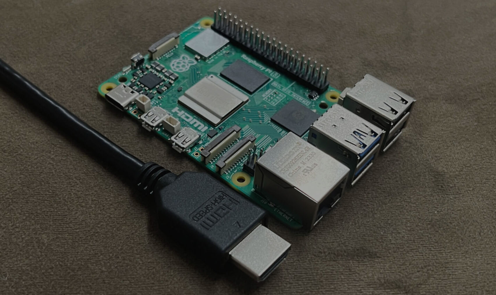
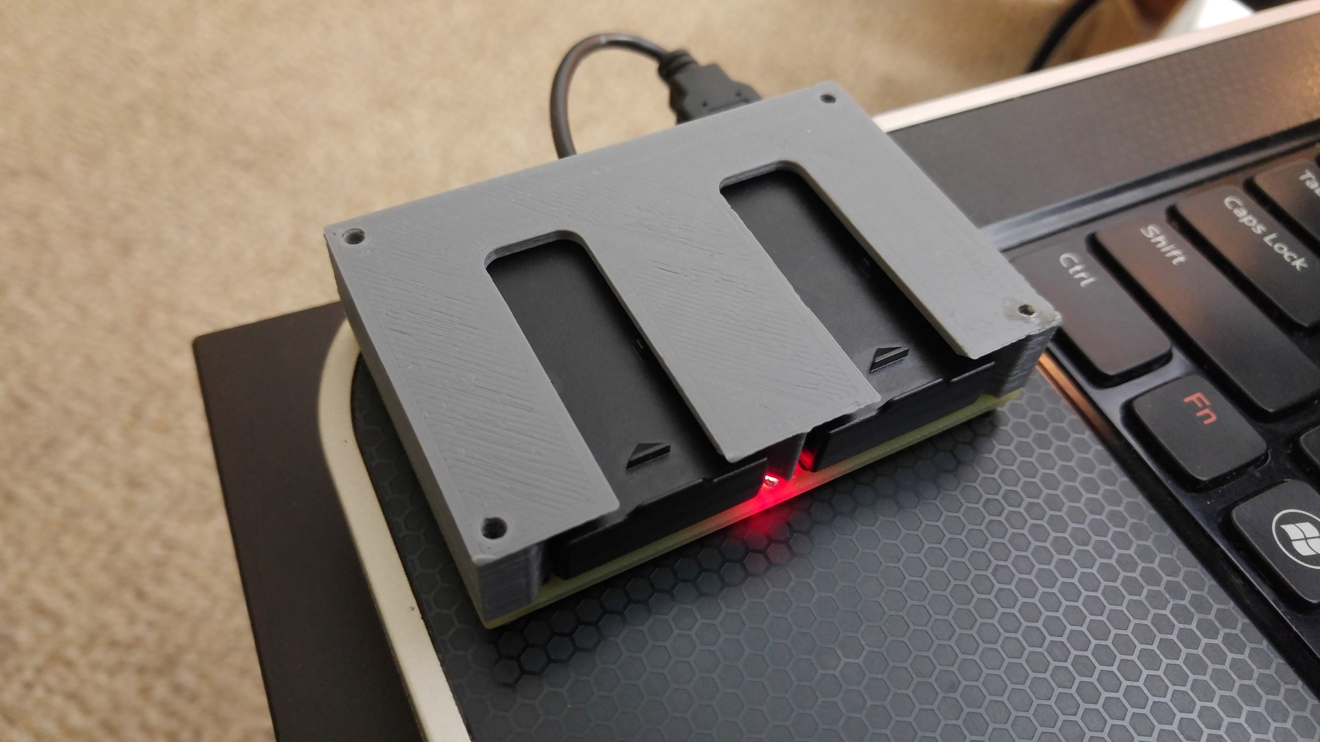
Using a Laptop as a Monitor for a Headless Raspberry Pi
You’ve got a shiny new Single Board Computer, like a Raspberry Pi, for a headless project, but then you’re hit with the realization – no monitor in sight for the initial setup. Fear not, though, if you’ve got a laptop nearby, there’s a potential workaround waiting for you (and me). What are SBCs? On a single, compact circuit board, Single Board Computers (SBCs) pack a punch, integrating all the vital components of a computer. This includes a processor, memory, storage (via microSD cards or eMMC), and a range of input/output interfaces (such as USB ports, LAN, HDMI, and GPIO pins), along with power management circuitry. Their small size, affordability, and versatility make SBCs a go-to solution for a wide range of applications. There are some key points of why you would like to use an SBC: Some well-known examples of single-board computers include the Raspberry Pi series, Arduino boards, BeagleBone, and Odroid, among others. Each of these SBCs may have its own unique specifications and capabilities, catering to different user needs and project requirements. What kind of connection most SBCs have? Single-board computers (SBCs) typically feature different kind of connection options to facilitate their use in various applications. These connections can vary depending on the specific SBC model, but here are some of the most common types of connections found on many SBCs: It’s important to note that the availability and types of connections can vary…
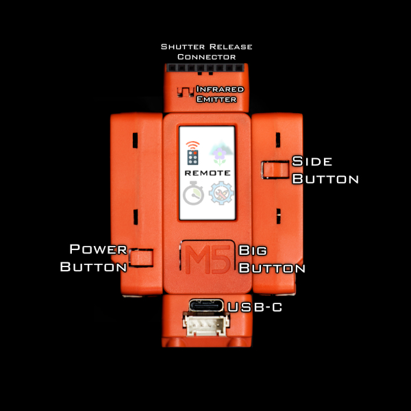
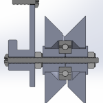
Wireless Camera Controller:Alpha-Fairy
I made(*) this tiny remote control for Sony Alpha cameras. Preface This is an open source firmware project. I wrote the source code for this project in Arduino flavored C++ and I am sharing it on GitHub. (*)I did not design the hardware nor do I offer it for sale. GitHub project main page Instructions for building and usage Features Minor Features Full Menu Map: The Story and the Challenge A while ago I owned a camera that was before bird tracking auto-focus was a well implemented feature, but got super envious when the Sony A1 was released. I ended up adding bird tracking to the camera myself, using a Google Coral to accelerate a simple pretrained neural network to point out birds and move the focusing point around on the camera. That project involved some reverse engineering of the Picture Transfer Protocol (aka. PTP) that is used by Sony between their camera and their PC app. Then I got interested in macro photography. There’s a technique in macro photography called Focus Stacking that I wanted to use but it’s a bit of a pain, some other camera brands offer this features in-camera, but not Sony. Knowing that it can be implemented with some commands over PTP, I wanted to add this feature to the camera as an external accessory. But this time it had to be a tiny battery powered wireless device. Here’s a demo video of Alpha Fairy doing focus…

Toaster Oven Conversion: A DIY Reflow Soldering Solution
As I get more serious into my electronics hobby, I need to work with more SMD components. Some component packages are very difficult or impossible to solder with a traditional soldering iron. To solve this problem, I decided to hack a toaster oven to become a reflow soldering oven. Basically, to perform reflow soldering, solder paste is placed on a printed circuit board, and the components to be soldered is placed on top of the solder paste. When the oven heats the solder paste past the melting temperature, the solder paste melts and solders the component to the circuit board. To control the oven’s temperature, I created my own reflow toaster oven controller circuit. This circuit uses an ATmega32U4 microcontroller to monitor the oven’s temperature using a thermocouple and AD595AQ, and then control the oven’s heating element using a solid state relay. The controller features USB logging/debugging, USB bootloading, a graphic LCD display, and 3 buttons. The firmware features tweaking for all settings, manual temperature control, manual heating element control, and automatic temperature profile control (with a nice temperature history graph display). This circuit will plug into a wall outlet, and the oven will plug into this circuit, while the solid state relay basically acts as a switch between the wall outlet and the oven’s heating element. Safety is the main design objective (but some things were limited by cost), and ease of use is the…
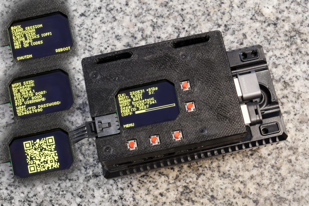
Bucket: Intelligent Photo Backup and Selector
This is a tool made to transfer and backup photos from a professional camera while in-the-field. Built with a Raspberry Pi 4 (other Pis will work too, it’s all just Python code), using Wi-Fi for file transfers and USB disks for file storage, powered by batteries. While on photography trips, I’m running out of storage on my camera’s memory cards. They are expensive memory cards and I can’t buy too many of them ($400 for 160 GB, and the camera needs two). I don’t want to go back to a hotel before clearing out a memory card either. So the strategy is to wirelessly transfer the files into a cheaper-slower-but-bigger storage device (TB sized USB disks) simultaneously as the camera is shooting. The slower speed should be fine because the transfers will happen during the down-time, when I’m walking around not taking pictures. USB disks at this size typically cost just a bit over $100 (genuine, authentic, non-scam ones) and require USB-3.0 ports. Once the photos are in the bigger storage device, I can clear the expensive-and-smaller memory cards without going back to a hotel, using in-camera quick-reformat. This project needs to be done by late June of 2022, my next vacation. (I hope this explains some very weird decisions I’ve made) Features ♦ Runs as a FTP server for professional cameras to transfer photos into. A redundant copy of the photo is made if 2…

Geeky Stained Glass
It’s nearly Christmas again! I’ve started to learn a new craft, an ancient one, and started to mix it up with modern technology. Behold, stained glass suncatcher with embedded LEDs This is essentially black magic to most glass artists and a huge “duh” moment to all the makers and engineers. I’ve been asked to teach how this is done… Just a teaser preview of my second project Before I start talking about the geeky part, I’d like to summarize the basic steps in making a basic piece of stained glass artwork like this:
EaseRobot – A Cutting-Edge Autonomous Robot
Welcome to EaseRobot, a cutting-edge autonomous robot designed to revolutionize home automation. This innovative DIY robotics project aims to create a sophisticated house-bot that can navigate and interact with its environment. In this series, we’ll delve into the project’s details, starting with the concept, hardware selection, and initial software development. Inspired by the possibilities of modern robotics, EaseRobot is built around a Raspberry Pi 3, Model B, leveraging its processing power and versatility. By harnessing the capabilities of the Robot Operating System (ROS) and Raspberry Pi, we can focus on developing the robot’s features rather than building a custom processor board from scratch. EaseRobot is designed to perform various tasks, including facial recognition, speech synthesis, and autonomous locomotion. Our robot will be equipped with a 7″ touchscreen display and a camera module, enabling it to interact with users and navigate its surroundings. With ROS, we can develop and test nodes for the system, simulate the robot’s behavior, and refine our code. In this project, we’ll explore various “missions” that EaseRobot can perform, starting with the ability to take messages to specific individuals. We’ll break down this mission into smaller design goals, including face recognition, speech synthesis, locomotion control, and navigation. Join us on this exciting journey as we bring EaseRobot to life and explore the possibilities of autonomous robotics. Getting Started EaseRobot Tutorial 1 EaseRobot – A Cutting-Edge Autonomous Robot First installment in a series on…
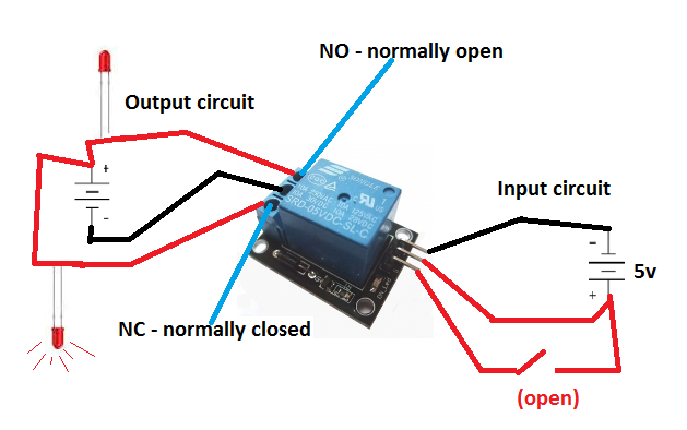
From Scratch to Smart: Creating a Custom Lock with EaseLock
Create a custom smart lock device for your existing door that integrates an Atmega328 microcontroller, HC-05 Bluetooth module, and relay module, enabling remote operation from any paired Android device. In this project, We will show you how to build a comprehensive prototype of smart lock step by step with minimal cost. The initial intent with this tutorial was to show you that you can make build this project even if you have little experience with all of the various parts (AVR chips, Bluetooth, Android). We still believe you can if you follow the steps in this tutorial. Getting Started Hardware Tutorial EaseLock Hardware Tutorual Create a custom smart lock device for your existing door that integrates an Atmega328 microcontroller, HC-05 Bluetooth module, and relay module, enabling remote operation from any paired Android device. In this project, I will show you how to build a comprehensive prototype of smart lock step by step with minimal cost. Introduction Developing a product that goes beyond software requires mastering multiple technologies, which can be a daunting task. However, this diversity can also be the most fascinating aspect of the project. Below is a rough diagram that provides a comprehensive overview of the project. It illustrates all the necessary components and should give you a general understanding of how this system functions. In general, this project allows to open your door via Bluetooth. Components Summary Essential Hardware Components for the Project:…