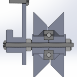
For my antweight combat robot DetCord, I wanted a wheel that could improve upon the Banebots wheels that I used before. I wanted something shock absorbing, which would extend the life of my gearboxes. The tires need to be soft and have high traction. The wheel does not have to be very strong because the robot has thick armour to protect the wheels.
I ended up with a cool way to make a wheel that’s cleaner than the more popular methods I see on the internet!
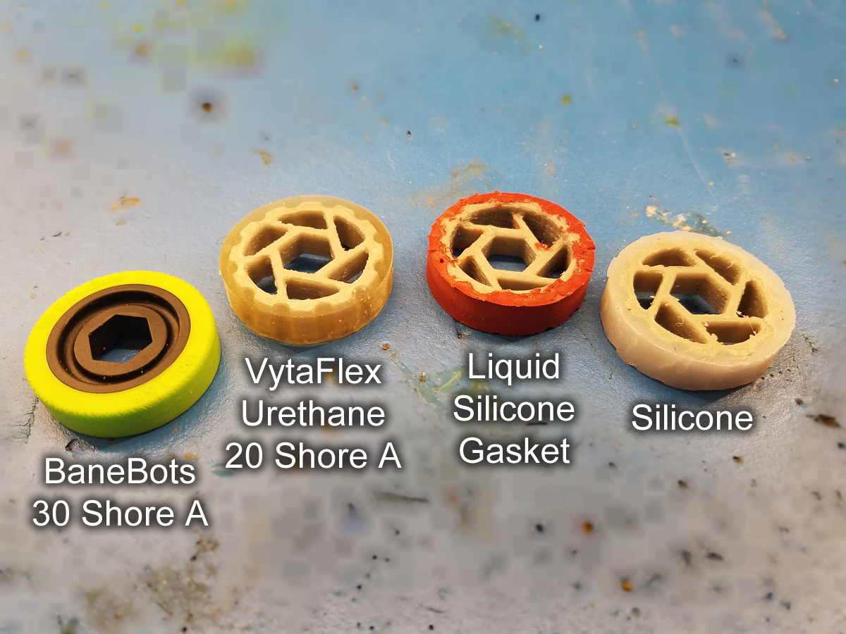
I can print the wheel hub in TPU with spiralling spokes for shock absorbtion. But 3D printed TPU is shore 95A and so doesn’t grip as well as the shore 30A Banebot wheels I already have. I need a tire that’s a softer material with high traction.
I researched and found plenty of resources on how to make wheel molds for liquid urethane mixtures. But searching around I can’t find liquid urethane in low quantities, and the casting process sounded like a pain.
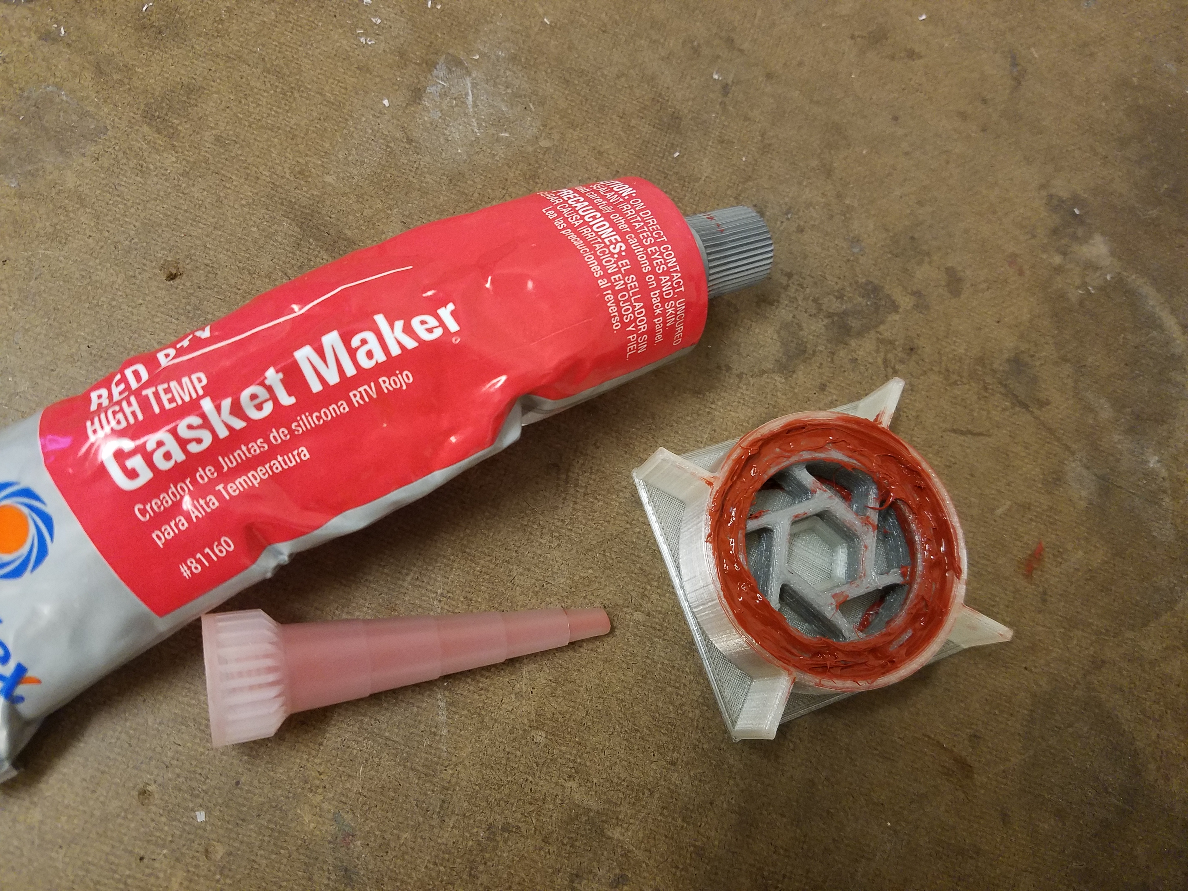
I thought this would be a good challenge, the rules are: only use materials I can 3D print easily, and a single liquid that can be purchased in low quantities and doesn’t require mixing. So I ended up choosing TPU for the wheel hub, PVA for the tire mold, and “liquid gasket” as the tire.
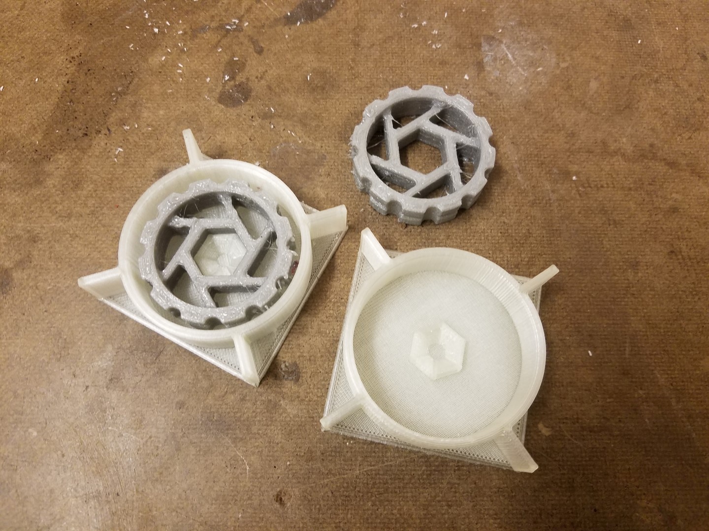
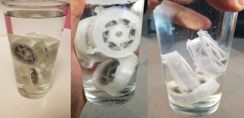
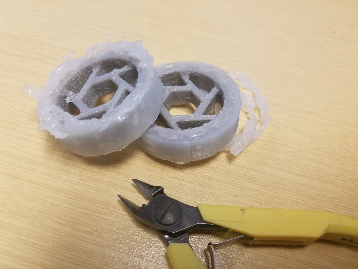
My mold is printed out of PVA, it’s a water soluble plastic. So when the liquid rubber cures, I can just dunk the whole mold in water to release it. No mold release agent is required!
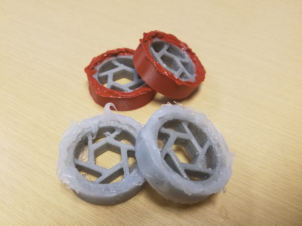
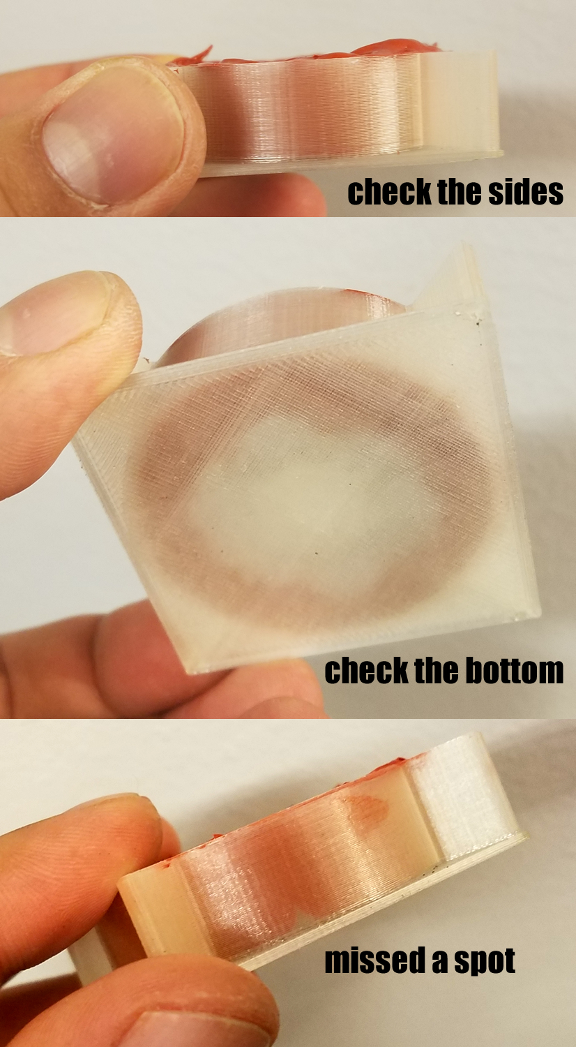
Squeezing in the liquid gasket was easy because my 3D printed TPU hub had a lot of flex, and I also had a lot of circular cutouts to put the nozzle into. When filling in the liquid, remember to check if you’ve filled in all the crevices. PVA is translucent and the liquid gasket is red, so checking is very easy to do.
I tried both liquid gasket and ordinary silicone window sealant. The ordinary silicone is slightly more slippery but cures in half the time. The liquid gasket is the winner here between these two.

I made the mold very tall, I am not experienced with how these chemicals cure and so I did the safe thing and overfill on purpose just in case it shrunk during curing, which meant I had to cut off the excess material after.
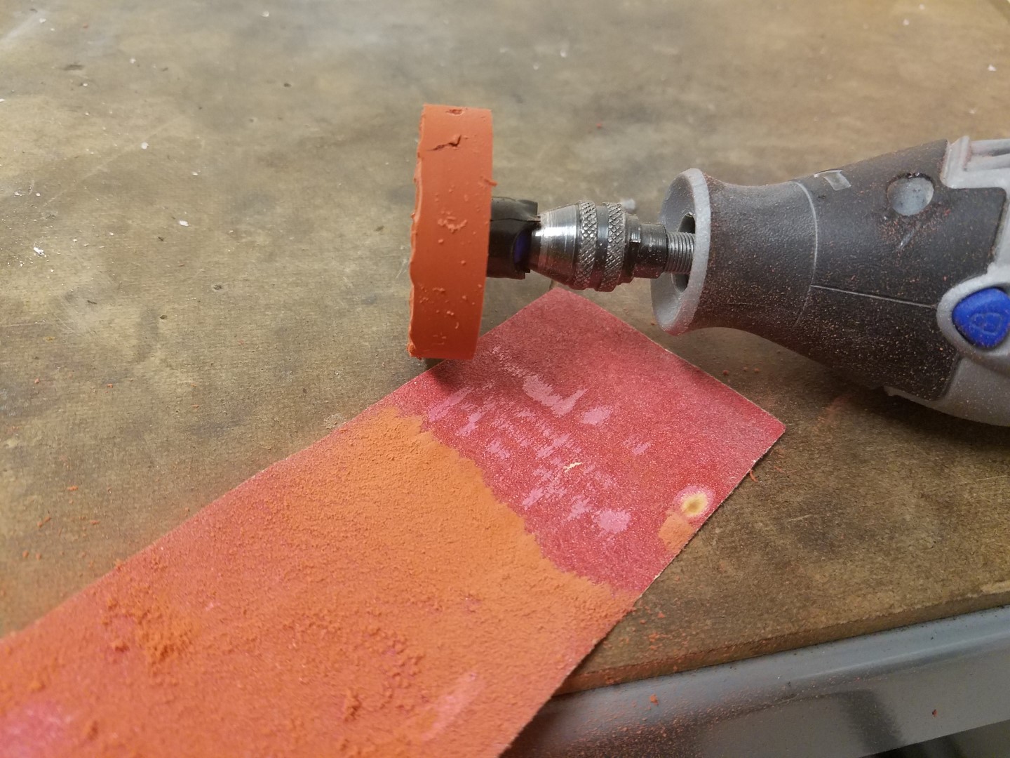
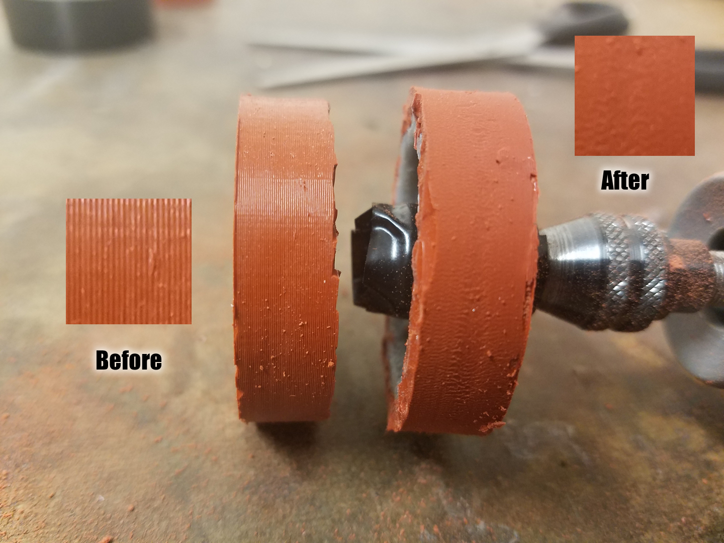
The mold had an extremely smooth inner surface (thank my Ultimaker’s print quality), with a bit of layer lines visible, this actually made the tire very slippery. So in the end, I roughed up the final tire with 120 grit sandpaper while spinning the wheel on a dremel. (sorry, the amount of dust this made is nasty, it negated my goal of being a clean process)
The liquid gasket tire is still less grippy than the Banebot wheels but it’s acceptable. My robot does not rely on pushing power as the horizontal spinner gives it more of a glass cannon fighting style. But keep in mind that this method will work with liquid urethane too, so if you need that extra grip, you can still use a PVA mold with liquid urethane.
I did eventually get around to trying liquid urethane. It was surprisingly easy and clean. It is much more viscous so I didn’t need to wreck my hands squeezing a tube. The final tire is very VERY grippy and definitely something that could be extremely competitive in robot sports.