Naked HDD Activity Indicator

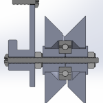
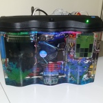
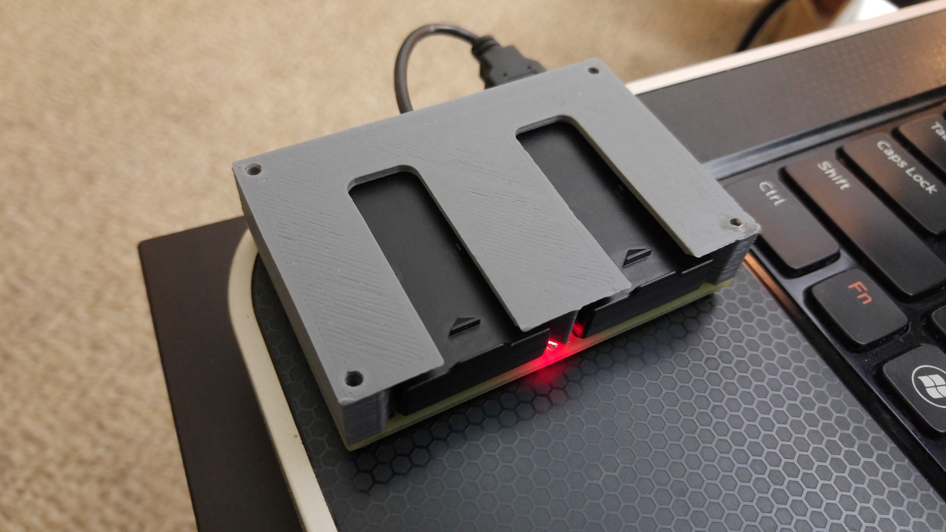
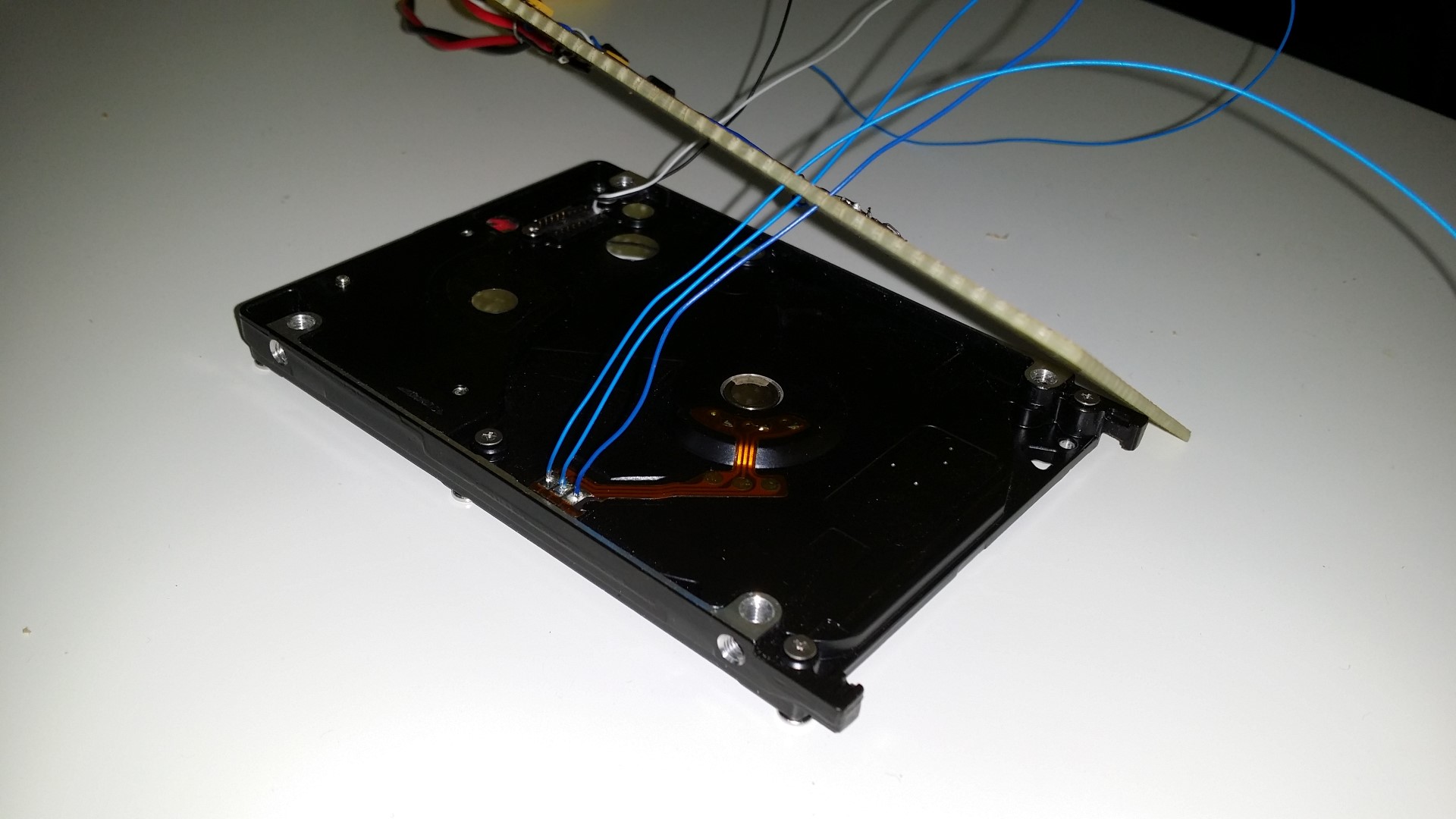
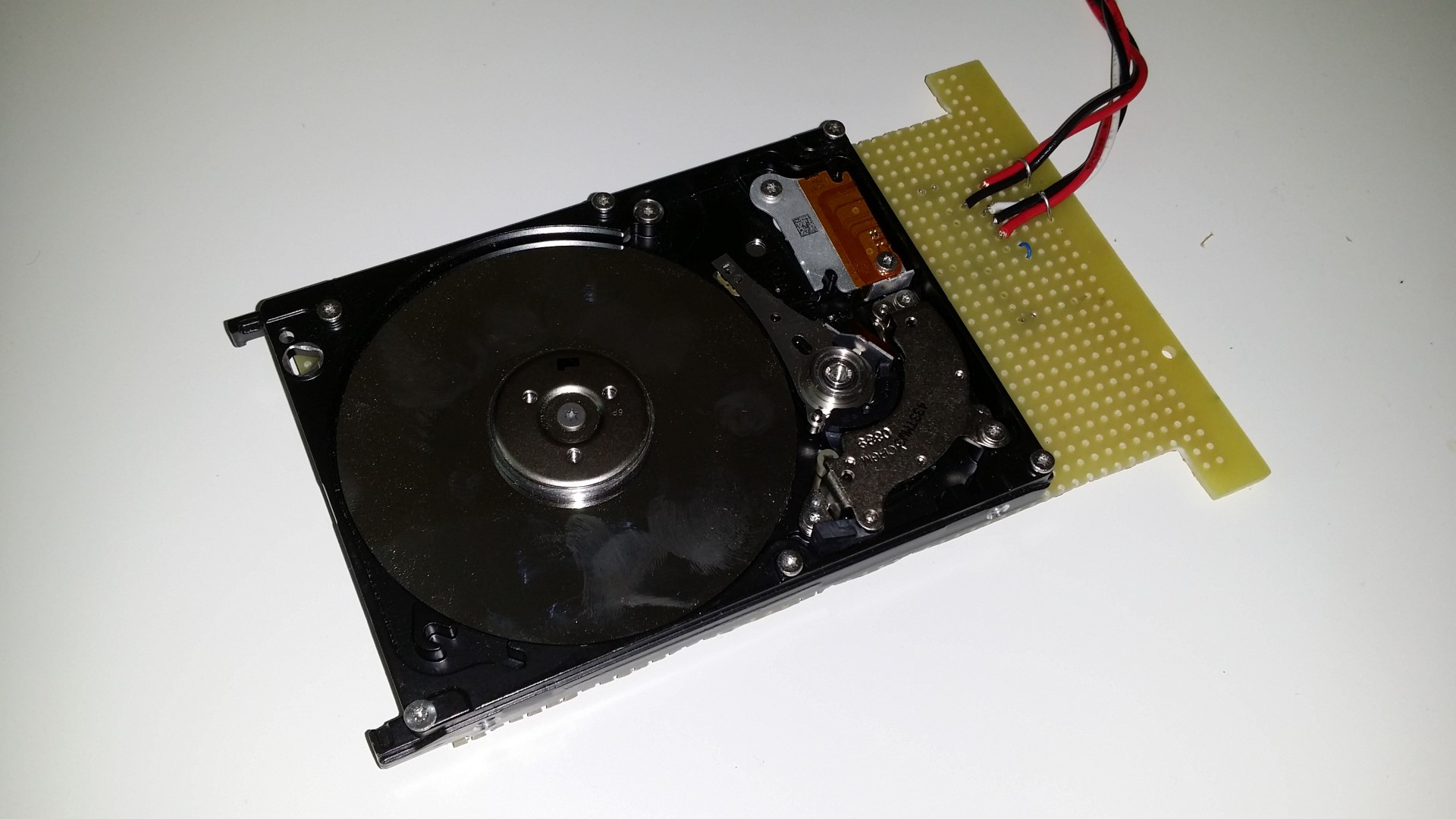
Remember my Aquarium Computer? I thought the SSD looked boring, so I put a old-school HDD inside with all the guts exposed, and wired it electrically to spin and swing when there is hard drive activity (when the HDD activity LED blinks).

20150314_160247 (Large)
20150314_161354 (Large)
20150314_161412 (Large)

But I have a deep dark secret…

OK I’ll be honest, this is a “failed” project. I considered it a failure because I got lazy and used a MTD6501 chip to spin the platter, but it always spins for a little bit and just stops. I don’t know why, I don’t see the power dipping on o’scope traces. That chip is designed for driving things like cooling fans.

Another reason why I think it’s a “failed” project is because IT IS ANNOYING AS HELL BECAUSE IT IS SO GOD DAMN FUCKING LOUD. Obviously it’s because my primitive circuit is simply using a MOSFET to shoot as much current through the coil as possible, thus smashing it from end to end. A better circuit would obviously use some form of current control, and obviously a real HDD circuit would control the coil with micrometer precision.

But it was still fun. I leave it disconnected.

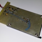
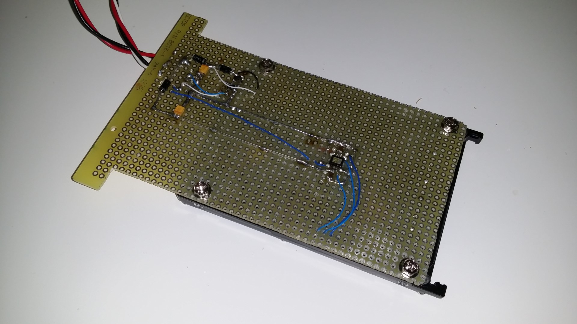
Here is the rough circuit:

circuit

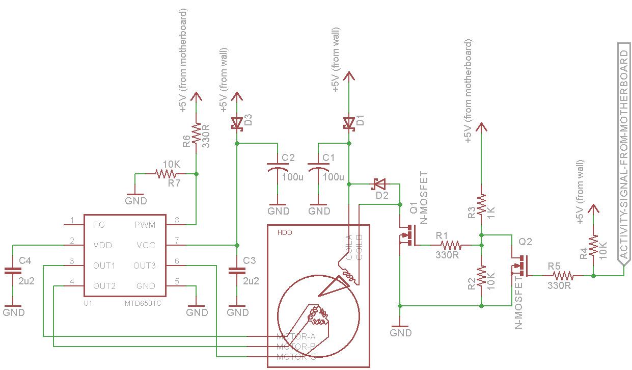
Yes, I understand I can make huge improvements, but I did it with spare parts in one day. Remember to check the polarity of the read head voice coil first!

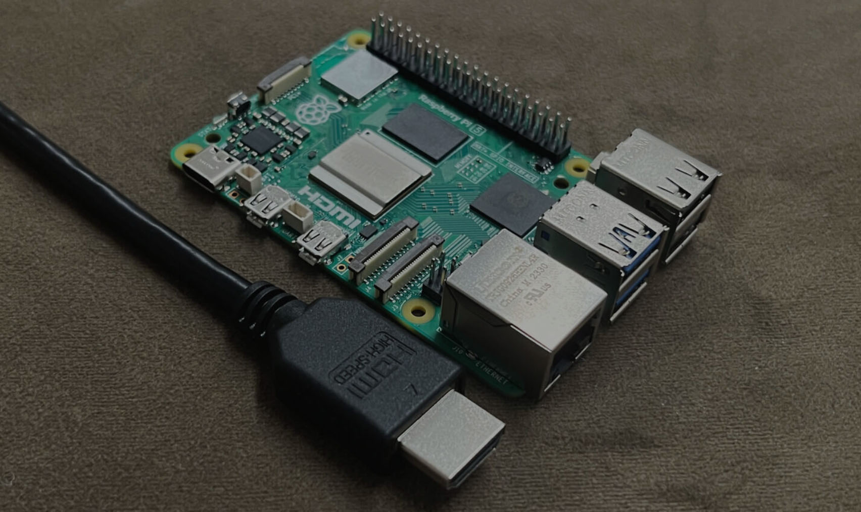
On a side note, if you simply power up a PATA HDD, it will spin without adding your own motor driver. But if you attempt to mess with the read head, I suspect it fails some sort of “self-test” and won’t spin anymore. Another approach to this project is to get a MCU with enough pins to use the PATA interface itself and actually perform random read operations.

A previous attempt of this project used power from the motherboard directly, but that caused my computer to not boot, I think the primitive way I am driving the voice coil is drawing too much current. This current implementation uses power from a 5V wall wart instead.

When I have time, I will reattempt this using a small microcontroller and PWM to control the voice coil.

  • Related Posts

    Upgrading an LC Meter Kit: A DIY Enhancement Project

    Upgrade Your Budget LC Meter Kit: A DIY Enhancement Project The HU-053 LC Meter kit is a budget-friendly option for measuring capacitance, inductance, and frequency, available online. With its easy-to-solder components and transparent acrylic enclosure, it’s a great weekend project for electronics enthusiasts. But how accurate is it, and can we make it better? Kit Contents and Assembly The HU-053 kit includes a double-sided PCB, a bag of components, a transparent acrylic enclosure, and all the necessary nuts and bolts for assembly. The assembled device measures 91 × 106 mm with a height of 28 mm, featuring an alphanumeric LCD, a 40-pin STC89C52RC microcontroller, a 3P4T function selection switch, and a ZIF socket for connecting the component to be tested. The unit is powered by a 5-V supply. Improving the LC Meter’s Accuracy After assembling and testing the device, we were disappointed to find that its accuracy was as low as its price. But this presented an opportunity to improve it! In this article, we’ll explore ways to enhance the HU-053 LC Meter’s performance, making it a more reliable measurement instrument. Download the article to learn how to upgrade your budget LC Meter kit and turn it into a useful tool for your electronics projects.

    Ultimaker2 Bearing Spool and Bearing Guide Upgrade

    This is an upgrade to the Ultimaker2 3D printer for people who have spools that do not fit the original spool holder, and spools that are too tight and thus do not feed smoothly, causing under-extrusion. It is composed of two assemblies: a replacement for the filament guide and a replacement for the spool holder. Both utilizes ordinary skateboard bearings to achieve smooth rotation. The conical shape of the spool holder allows for any sized spool to be used, easily swapped because it uses a wing nut. Files are available on YouMagine. I want to emphasize that I am sharing the STEP files, not just STL, because STL are harder for people to import and modify than STEP files. SolidWorks files are also provided. The cross section images shows you how to assemble the upgrade parts. The screw diameters are #6 for the filament guide and 5/16″ for the spool holder. Please figure everything else out from the cross section images.

    Related Articles

    Accurate EV Power Consumption Measurement: Introducing the LeoINAGPS System

    • August 25, 2024

    Upgrading an LC Meter Kit: A DIY Enhancement Project

    • August 25, 2024

    Aquarium Computer

    • August 6, 2024
    Aquarium Computer

    Ultimaker2 Bearing Spool and Bearing Guide Upgrade

    • August 6, 2024
    Ultimaker2 Bearing Spool and Bearing Guide Upgrade

    3D Printed Battery Recharge Dock for Parrot Rolling Spider

    • August 6, 2024
    3D Printed Battery Recharge Dock for Parrot Rolling Spider

    Using a Laptop as a Monitor for a Headless Raspberry Pi

    • March 7, 2024
    Using a Laptop as a Monitor for a Headless Raspberry Pi