Wooden Orrery: Laser Cut Project

Orrery – Laser Cut Wood Project

5 Replies

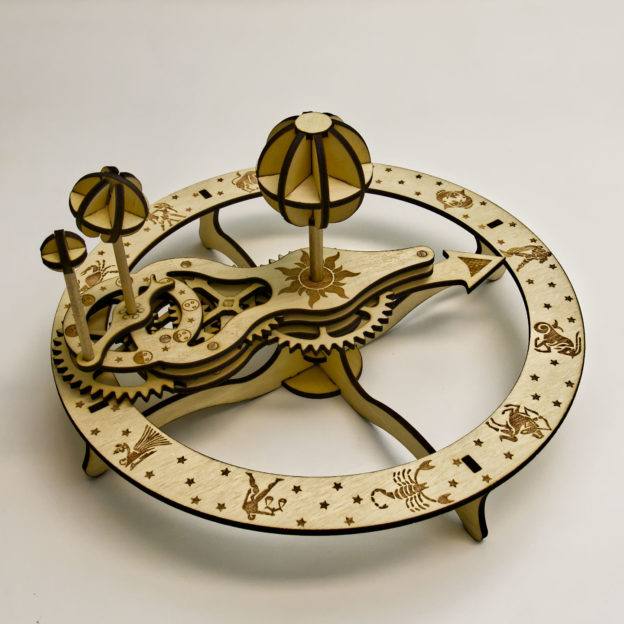
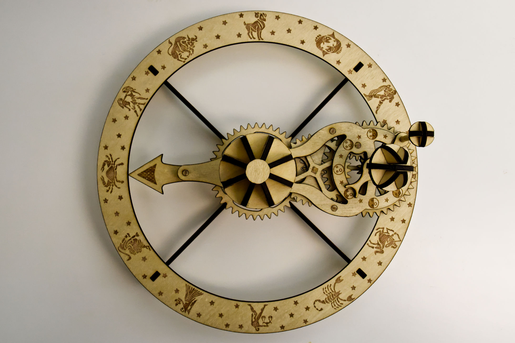
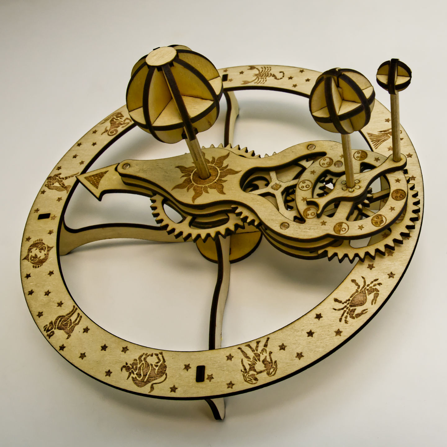
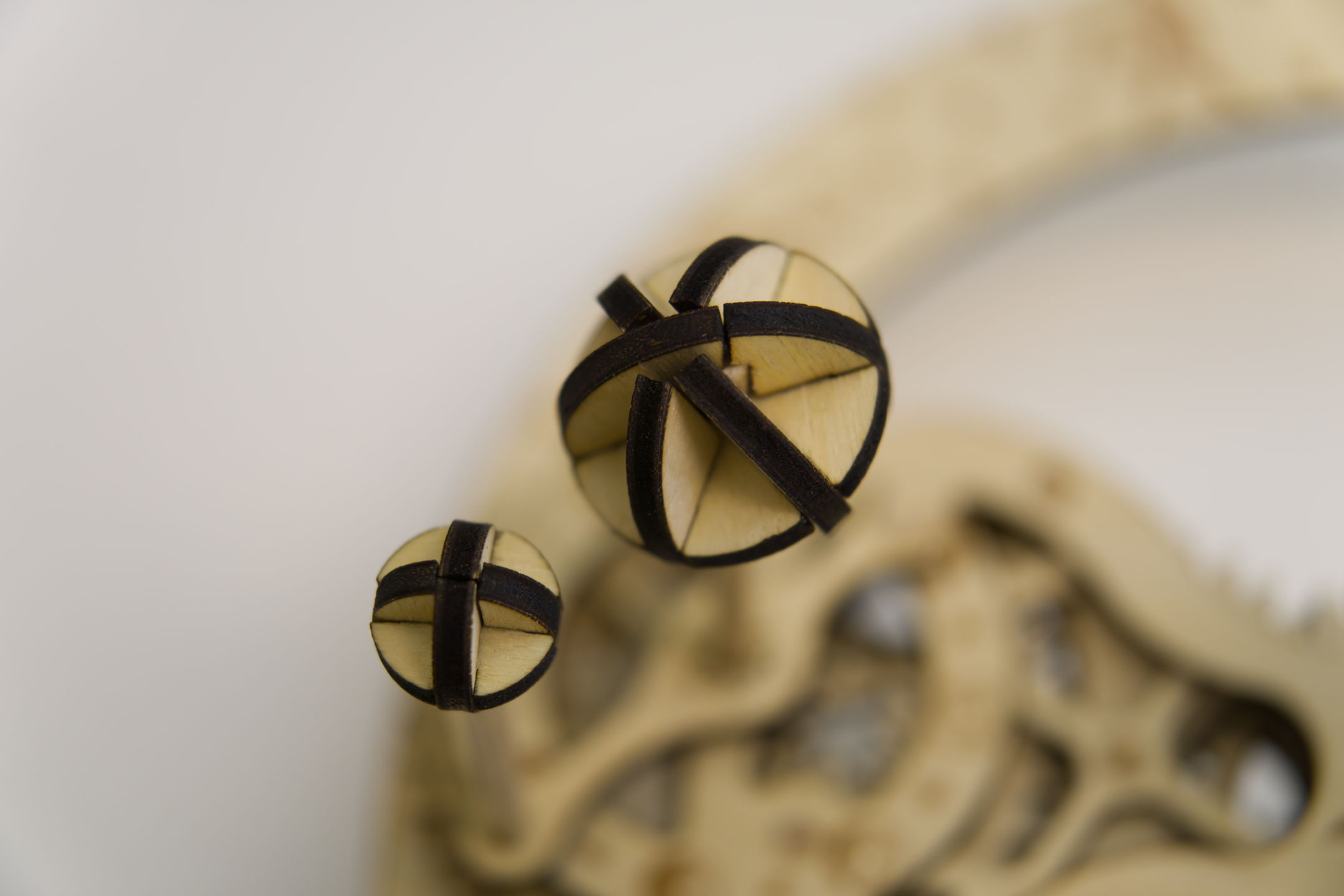
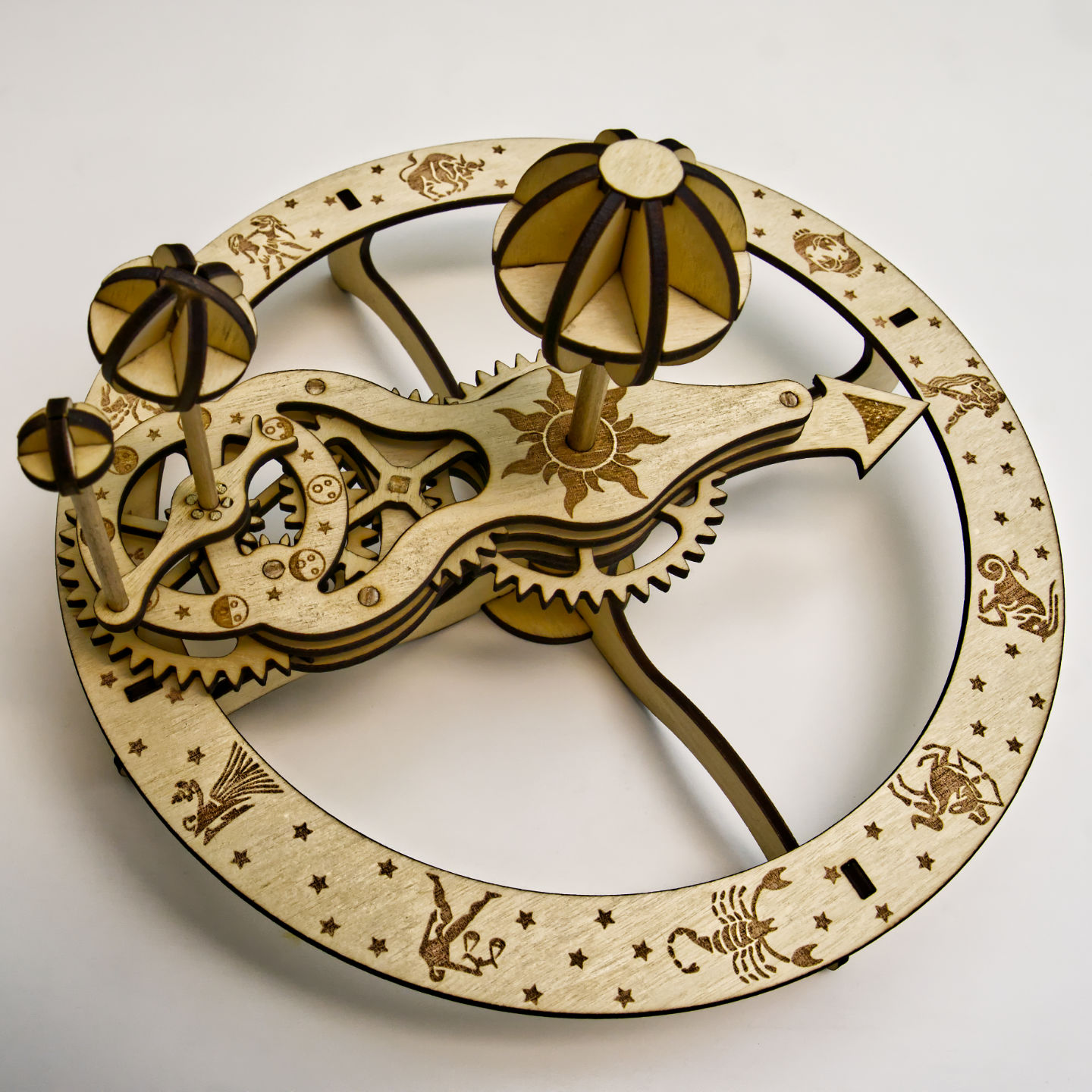
I’m having so much fun with my new Beamo laser cutter! I designed and made this wooden orrery with my Beamo. It’s a mechanical toy that depicts the position of the Earth and Moon as they orbit each other and the Sun, with artwork showing the moon phases and Zodiac. See more pictures and animation:

All files are open source and available on my GitHub repo (click here)!

I have provided the two SVG files to be cut on the laser cutter, optimized for the Beamo but should work on any other laser. The 3D models I designed using SolidWorks is also available. Assembly instructions are provided in the repo as well.

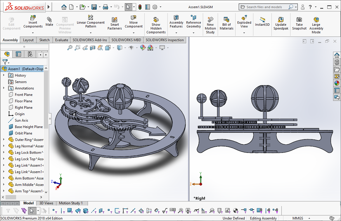
Originally designed in SolidWorks. The parts were then exported to SolidWorks drawing files, then exported to DXF files, then imported into Inkscape to be edited as SVG files.

Inside Inkscape, paths were joined together to optimize cutting. Paths that represented circles, squares, and slots, were converted into basic shapes so cut tolerances can be adjusted. Finally, the cutting order was organized into layers. Beam Studio will import the layers in the order you defined them.

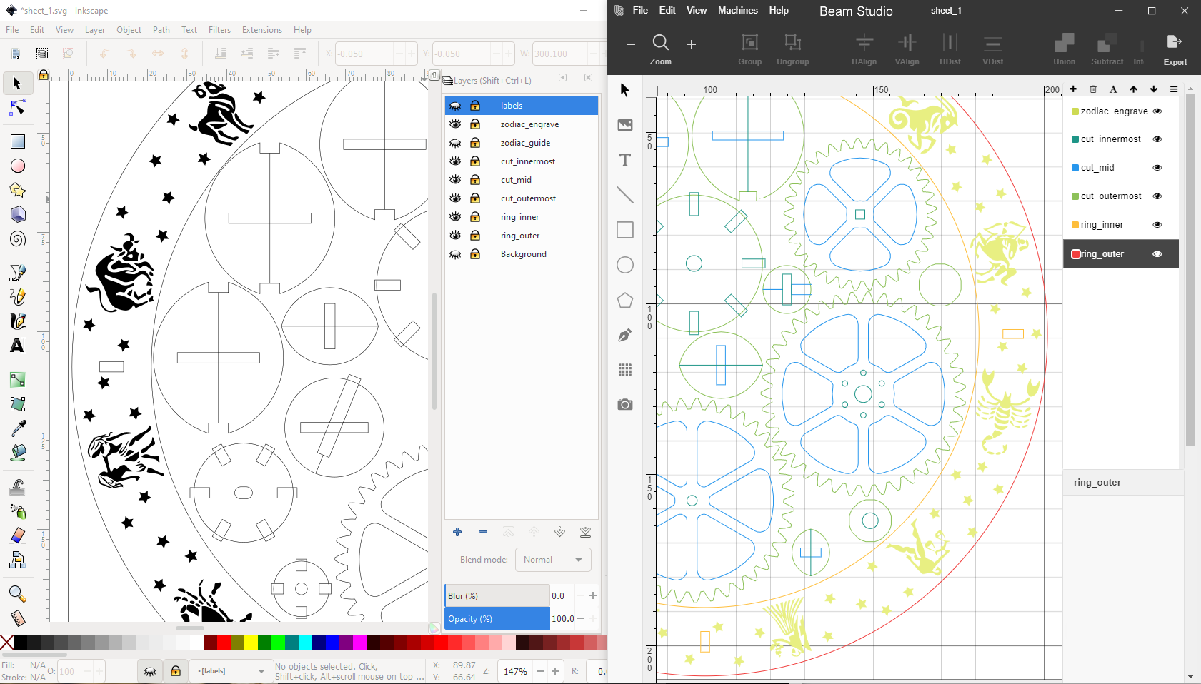
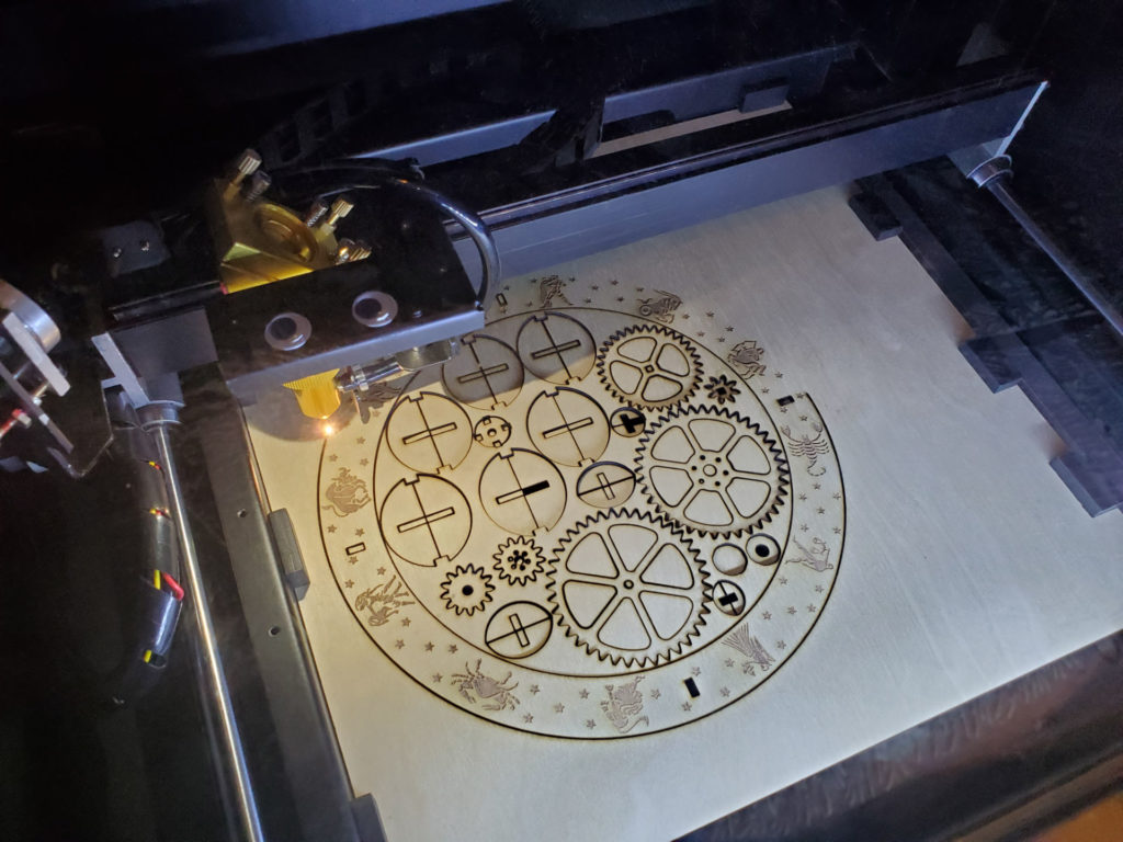
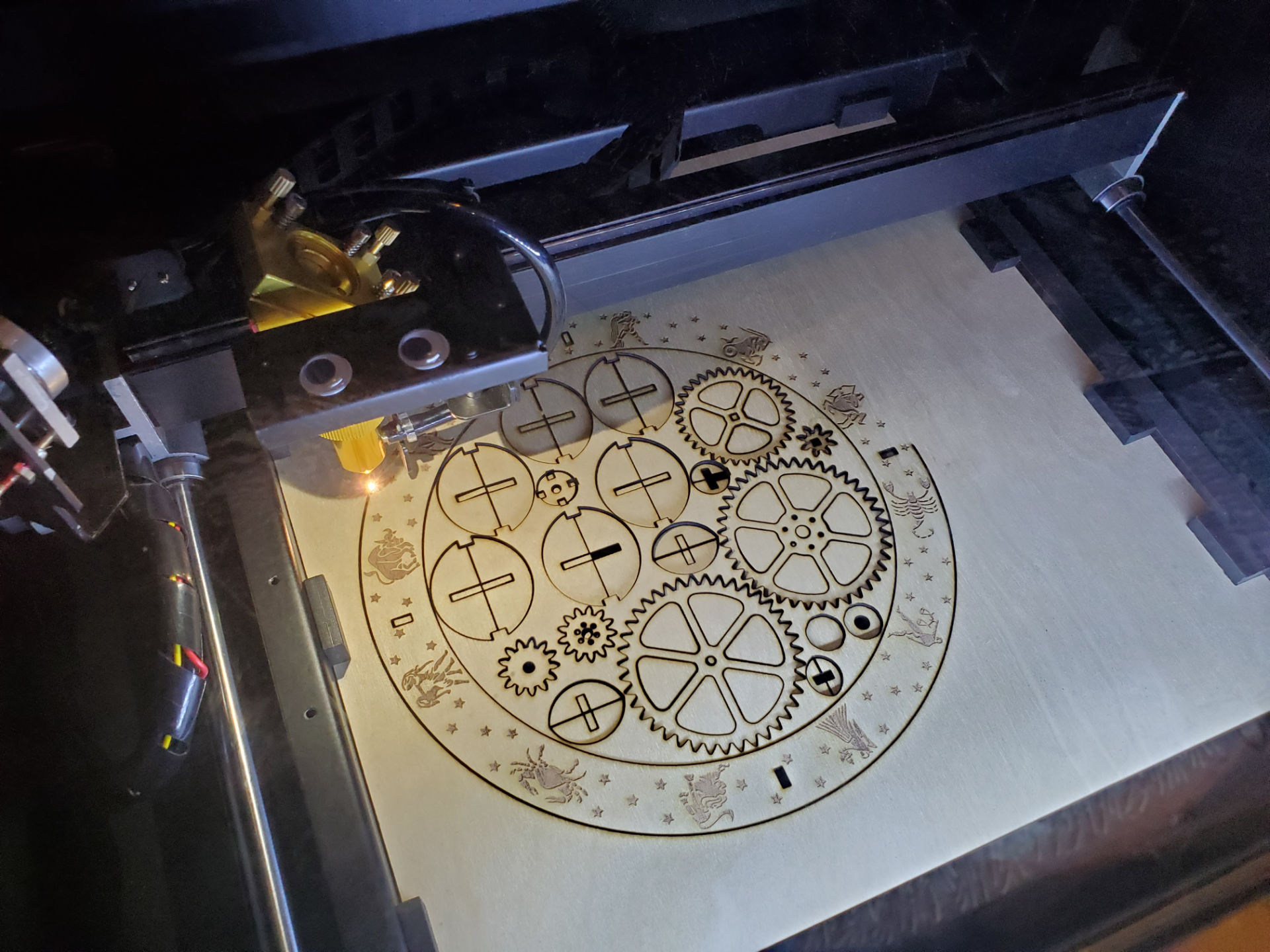
I learned the hard way that you need to make inner cuts first before outer cuts. Otherwise, if you do an outer cut first, the piece will move after being cut free and fall onto the laser’s honeycomb bed. This means the inner cut will be off target.

I also discovered that you can flatten plywood down onto the honeycomb bed using magnets!

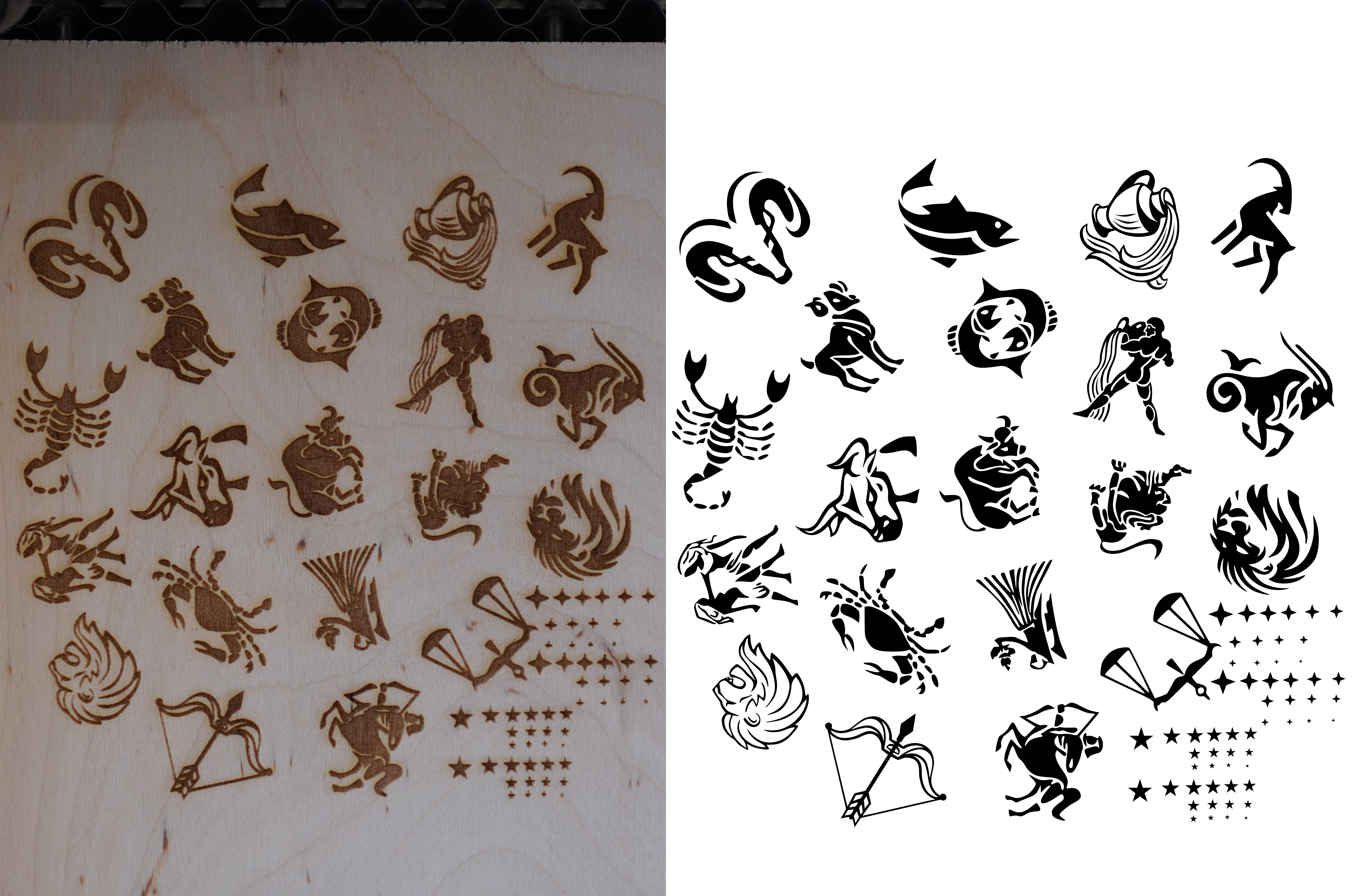
All the artwork had to be tested to see if the resolution of the laser was enough, and re-adjusted if lines were too thin or too thick. I did this with a test etch on a piece of scrap wood.

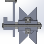
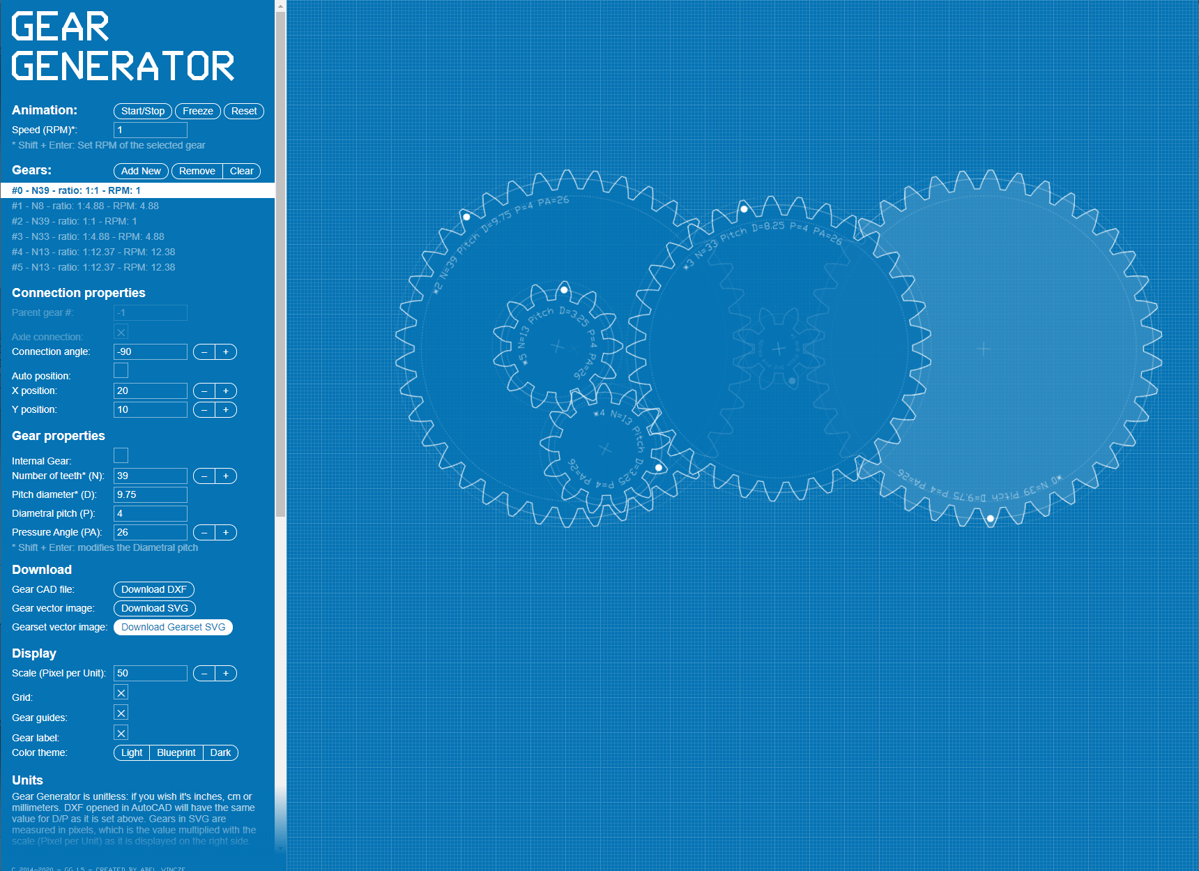
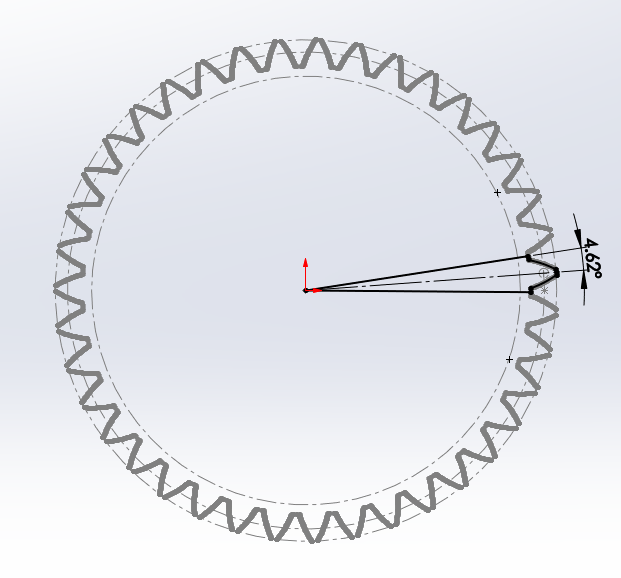
The gears were generated by https://geargenerator.com/. The gear ratios make the Moon phases and Earth seasons reasonably accurate (view the screenshot to see the ratios being used). The DXF files were imported into SolidWorks.

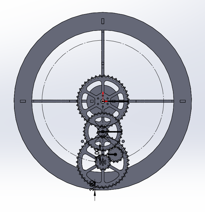
The above screenshot shows how the gear diameters and positions were determined. The circles in the drawing indicate the gears’ pitch diameter, and those circles are tangentially constrained together.

Gear Generator’s output is very complex (thousands of line segments) and makes SVG processing much harder, so the imported image was simplified down to one tooth, the complex segmented curvature is simplified down to one arc. The sketch is shown in the screenshot above.

Related Posts

Introduction to tinyAVR Microcontroller Attiny404 Architecture, Features, and Related Registers with a Simple Code Example

In this continuation of the tinyAVR tutorial series, this blog post delves into the AVR CPU architecture, capabilities, and registers. Table of Contents Features Overview AVR is a well known 8-bit CPU. The CPU is a heart of the device which can access memories, do calculations, execute instructions, control peripherals as well handle interrupt routines. Most part of this post is based on the official Attiny404 documentation, so for in-depth info check the datasheet. Architecture AVR CPU uses a Harvard architecture with separate buses for program and data. While one instruction is being executed by the CPU, the second is being fetched from the program memory – this pipeline allows instructions to be executed on each clock cycle. As you can see in the image above, the CPU has ALU – Arithmetic Logic Unit. It can do logic and/or arithmetic operations between two registers or a constant value and a register. Also, ALU can execute single-register operations. When the ALU finishes an arithmetic operation, the STATUS register gets updated with the information about the operation end result. The ALU can directly access to a register file which consists of 32 8-bit general purpose working registers. All these registers have single clock cycle access time. To sum up, this allows single cycle arithmetic operations between two registers. Memory overview The program memory bus is directly connected to Flash, the addresses start from 0x0000. Whole data memory space is…

Wireless Camera Controller:Alpha-Fairy

I made(*) this tiny remote control for Sony Alpha cameras. Preface This is an open source firmware project. I wrote the source code for this project in Arduino flavored C++ and I am sharing it on GitHub. (*)I did not design the hardware nor do I offer it for sale. GitHub project main page Instructions for building and usage Features Minor Features Full Menu Map: The Story and the Challenge A while ago I owned a camera that was before bird tracking auto-focus was a well implemented feature, but got super envious when the Sony A1 was released. I ended up adding bird tracking to the camera myself, using a Google Coral to accelerate a simple pretrained neural network to point out birds and move the focusing point around on the camera. That project involved some reverse engineering of the Picture Transfer Protocol (aka. PTP) that is used by Sony between their camera and their PC app. Then I got interested in macro photography. There’s a technique in macro photography called Focus Stacking that I wanted to use but it’s a bit of a pain, some other camera brands offer this features in-camera, but not Sony. Knowing that it can be implemented with some commands over PTP, I wanted to add this feature to the camera as an external accessory. But this time it had to be a tiny battery powered wireless device. Here’s a demo video of Alpha Fairy doing focus…

Leave a Reply

Related Articles

Accurate EV Power Consumption Measurement: Introducing the LeoINAGPS System

  • August 25, 2024

Upgrading an LC Meter Kit: A DIY Enhancement Project

  • August 25, 2024

Aquarium Computer

  • August 6, 2024
Aquarium Computer

Ultimaker2 Bearing Spool and Bearing Guide Upgrade

  • August 6, 2024
Ultimaker2 Bearing Spool and Bearing Guide Upgrade

3D Printed Battery Recharge Dock for Parrot Rolling Spider

  • August 6, 2024
3D Printed Battery Recharge Dock for Parrot Rolling Spider

Using a Laptop as a Monitor for a Headless Raspberry Pi

  • March 7, 2024
Using a Laptop as a Monitor for a Headless Raspberry Pi