This is a PPM signal splitter for use with the VEX radio transmitter/receiver kit sold at All Electronics (item is now gone from their web site, this article itself is extremely old and outdated because newer technology has arrived)
For $30 at All Electronics, you can buy a 6 channel radio transmitter and receiver. The transmitter is excellent for $30, trim, scaling, mixing are all programmable on the transmitter itself and it stores several configurations. The receiver only has one output pin, which outputs a PPM signal which needs to be split into individual channels in order to be able to control servos.
If you put the receiver right side up and with the socket facing you, the pin on the far left is the Vdd pin, connect this to a regulated 5 volt power supply, the middle left pin is the PPM output pin (it is open collector so a pull up resistor is needed), and the middle right pin is the Vss pin, connect this to your circuit’s ground, the far right pin is not connected to anything inside the receiver.

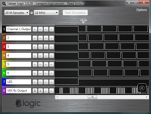
The 6 channel PPM signal has 7 periods of high and low pulses, each of these pulses all start with a high period of 500 microseconds, and a low period of varying lengths. The first low period is a sync pulse with a fixed low period of about 7 milliseconds, this exceptionally long low period indicates the next rising edge of the PPM signal will indicate the pulse start for channel 1. The period from the rising edge to rising edge of the a pulse is equal to the period of the high pulse that should be sent to the servo.

#include <avr/io.h>
#include <avr/interrupt.h>

#define BAUD 9600 // define baud rate here
#include <util/setbaud.h>

#define width_500 ((F_CPU * 5) / 10000) //  calculates ticks for 0.5ms

// pin and port renaming

#define in_port PORTD
#define in_pinin PIND
#define in_ddr DDRD
#define in_pin 6

#define LED_A_pin 4
#define LED_B_pin 5

#define out_port PORTB
#define out_ddr DDRB

// global variables

static volatile unsigned long ovf_cnt; // overflow counter
static volatile unsigned char chan_cnt; // channel counter
static volatile unsigned char mask_cnt; // used to determin next pin
static volatile unsigned int chan_width[8]; // stores pulse width in clock ticks
static volatile unsigned int chan_width_temp[8];
static volatile unsigned int last_capt; // time of last capture, used to find difference
static volatile unsigned char data_ready; // 1 if data is good, 0 if transmitter is off
static volatile unsigned char next_mask; // next port mask to apply
static volatile unsigned char busy_flag;

// input capture interrupt vector
ISR(TIMER1_CAPT_vect)
{
        out_port = next_mask; // apply port mask to pulse pin
        mask_cnt++; // next pin

        unsigned long t_ovf = ovf_cnt; // store overflow counter in case another overflow occurs during interrupt
        ovf_cnt = 0;

        unsigned long t_icr = ICR1; // convert to unsigned long

        // calculate total time using overflows and time difference
        unsigned long t = ((t_icr | 0x10000) - last_capt) & 0xFFFF;
        if(t_icr < last_capt)
        {
                t_ovf--;
        }
        t += 0x10000 * t_ovf;
        last_capt = ICR1;

        // if pulse is longer than 3ms, then it's a sync pulse
        if(t > width_500 * 6)
        {
                chan_cnt = 0;
                if(data_ready == 0)
                {
                        data_ready = 1;
                }
        }
        else // if pulse is shorter than 3ms, then it's a servo pulse
        {
                chan_width[chan_cnt] = t; // store time
                if(busy_flag == 0)
                {
                        chan_width_temp[0] = chan_width[0]; chan_width_temp[1] = chan_width[1]; chan_width_temp[2] = chan_width[2]; chan_width_temp[3] = chan_width[3];
                        chan_width_temp[4] = chan_width[4]; chan_width_temp[5] = chan_width[5]; chan_width_temp[6] = chan_width[6]; chan_width_temp[7] = chan_width[7];
                }
                chan_cnt++; // next channel
                if(chan_cnt >= 4 && data_ready != 0) // last channel, data is now good, reset to first pin
                {
                        data_ready = 2;
                        mask_cnt = 0;
                }
        }
        next_mask = _BV(mask_cnt); // prepare mask
}

// timer overflow interrupt vector
ISR(TIMER1_OVF_vect)
{
        ovf_cnt++;
        if(ovf_cnt >= 7) // if too many, then transmitter is missing
        {
                data_ready = 0;
        }
}

int main()
{
        // initialize variables

        ovf_cnt = 0;
        chan_cnt = 0;
        mask_cnt = 0;
        data_ready = 0;

        MCUCR |= _BV(PUD); // no pull-ups

        // initialize ports

        out_port = 0;
        out_ddr = 0;

        in_ddr |= _BV(LED_A_pin) | _BV(LED_B_pin);
        in_ddr &= 0xFF ^ _BV(in_pin);

        // initialize serial port

        UBRRH = UBRRH_VALUE; // set baud rate
        UBRRL = UBRRL_VALUE;
        UCSRB = _BV(RXEN) | _BV(TXEN); // enable port

        // initialize timer

        TCCR1B = 1 | _BV(ICES1); // start timer, input capture on rising edge
        TIMSK = _BV(TOIE1) | _BV(ICIE1); // enable interrupts

        sei(); // enable global interrupts

        while(1)
        {
                if(data_ready == 2)
                {
                        // enable output if data is good, light LED
                        out_ddr = 0xFF;
                        in_port |= _BV(LED_A_pin);
                }
                else
                {
                        // disable output if transmitter is missing, LED off
                        out_ddr = 0;
                        in_port &= 0xFF ^ _BV(LED_A_pin);
                }

                busy_flag = 0;
                if(bit_is_set(UCSRA, RXC)) // if command received
                {
                        unsigned char ch = UDR;
                        if(ch != 0) // if not null command
                        {
                                UDR = data_ready; // send status
                                busy_flag = 1;
                                unsigned int t = chan_width_temp[ch - 1]; // fetch from array
                                unsigned char h = (t & 0xFF00) >> 8; // get high byte
                                unsigned char l = t & 0xFF; // get low byte
                                loop_until_bit_is_set(UCSRA, TXC); // wait for finish
                                UCSRA |= _BV(TXC); // clear finished flag

                                // send two bytes, most significant byte first
                                UDR = h;
                                loop_until_bit_is_set(UCSRA, TXC); // wait for finish
                                UCSRA |= _BV(TXC); // clear finished flag
                                UDR = l;
                                loop_until_bit_is_set(UCSRA, TXC); // wait for finish
                                UCSRA |= _BV(TXC); // clear finished flag
                        }
                }
        }
        return 0;
}
I’ve recently rewrote the code from scratch, this is actually version 2. This new version eliminates any timing errors because everything is handled by the 16 bit timer’s input capture feature. Timer overflows help determine whether or not the transmitter is missing, and if it is missing, the port is disabled.
The serial port can be used to retrieve the pulse width of the channels. The baud rate is defined when you compile the code. First send the channel number, then wait for a three byte reply, the first byte will be 0x01 if the data is good, or 0x00 if the transmitter is missing, the next two bytes is the width of the channel pulse as a 16 bit integer, most significant byte being sent first. Pulse width is given in clock cycles and thus it varies based on the clock frequency you choose to use.
Hi, this is a comment.
To get started with moderating, editing, and deleting comments, please visit the Comments screen in the dashboard.
Commenter avatars come from Gravatar.