My trusty laptop is showing its age. 8 GB of RAM is not enough for the amount of 3D stuff I do now, and it can’t run the latest games at all any more. Since I got a full time job now (instead of a constantly travelling student), it’s time to get a desktop PC (first PC build, yay). But the process of building a PC is pretty boring, it’s just an exercise of picking out compatible parts for the right price. I decided to make it slightly more interesting by submerging the entire computer in a fish tank full of mineral oil.
UPDATE March 2015, I added a funny naked HDD activity indicator
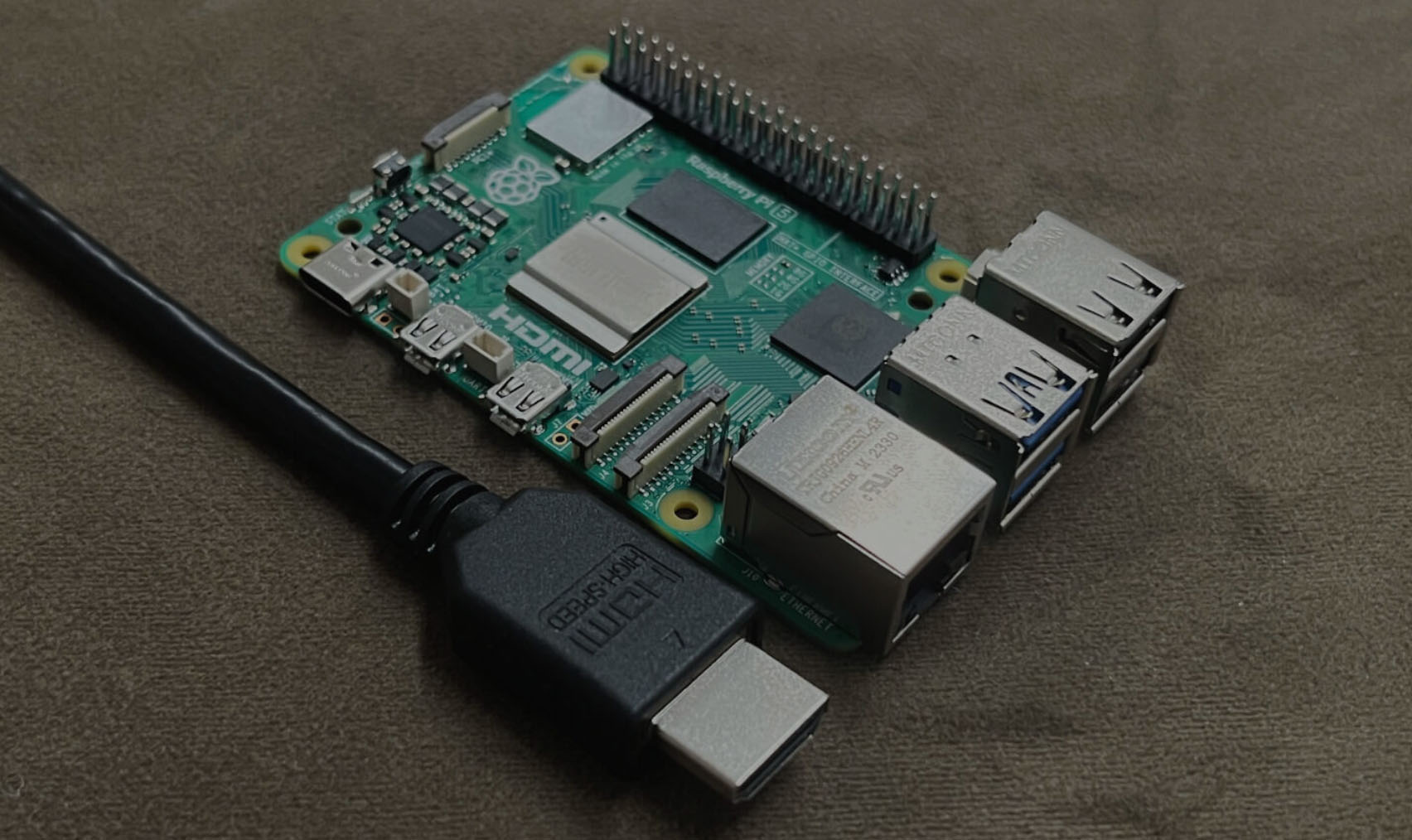
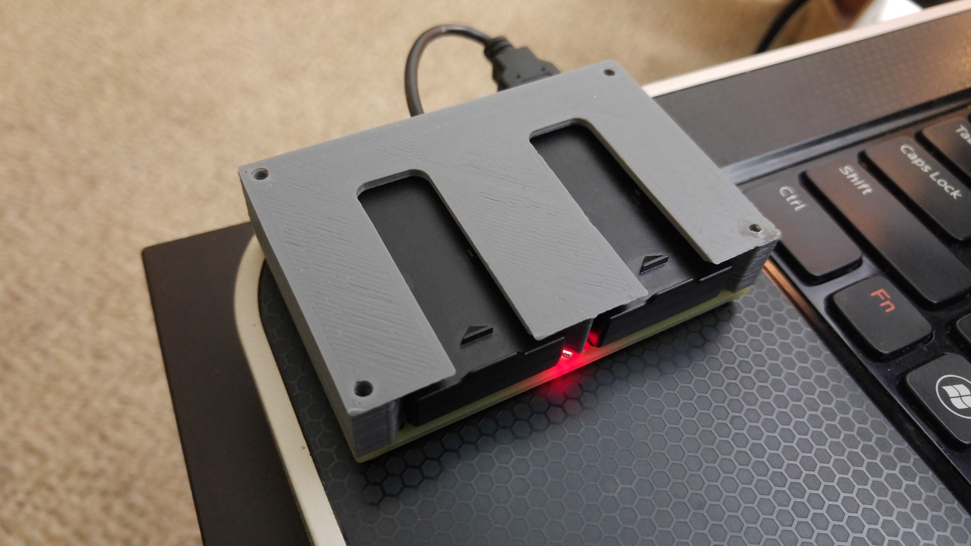
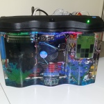
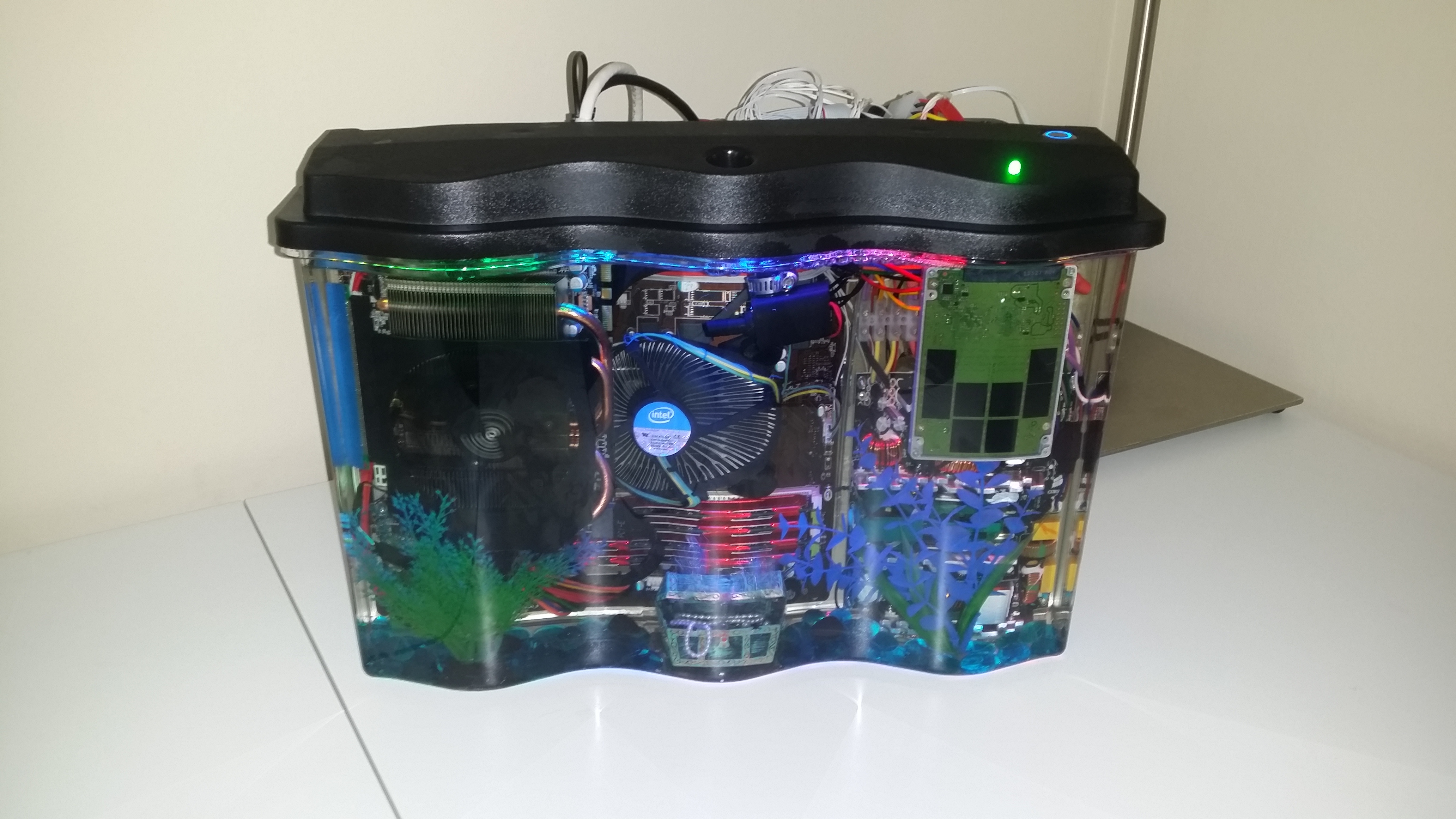
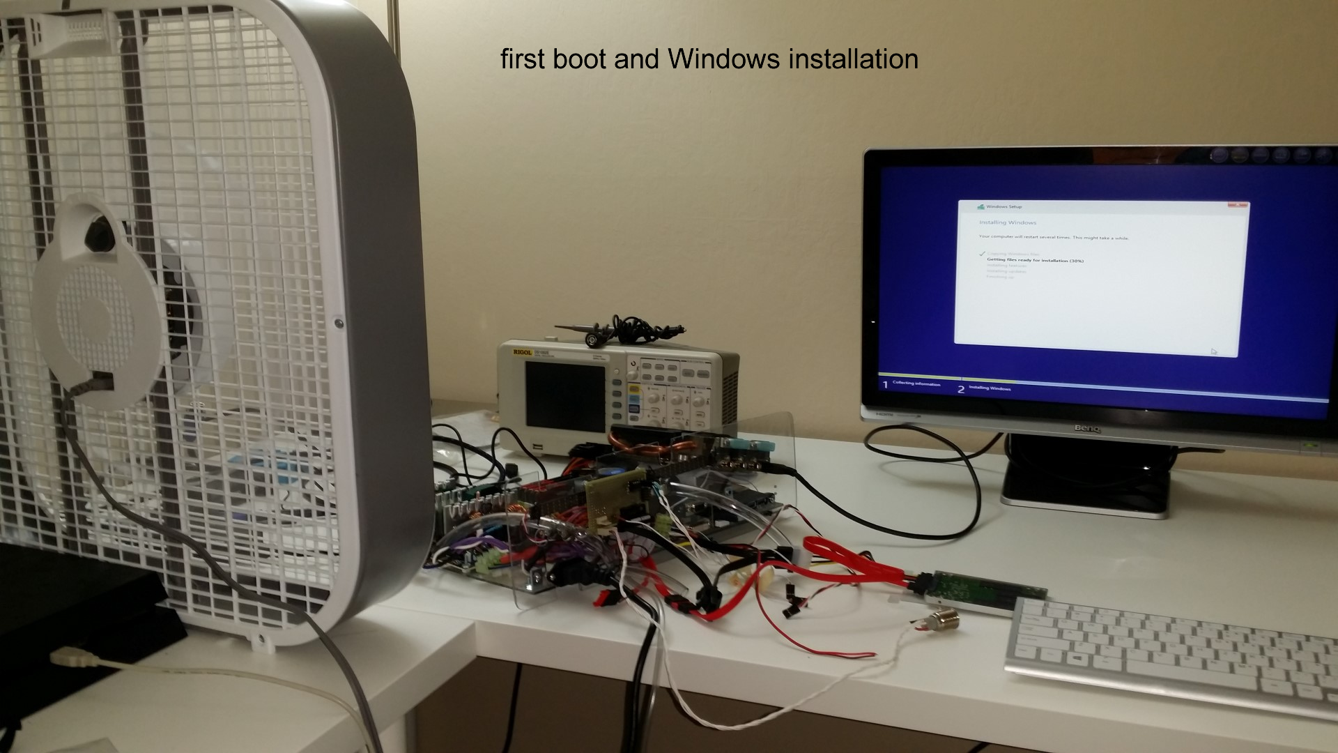
Some pictures from the build process

Short Story (long story later, technical details and stuff):
Intel i7 4790S, Nvidia GTX 970, H97M chipset, Corsair CX600M. Built onto a polycarbonate tray that is then dipped into a fish tank full of mineral oil. Fancy features like bubbling treasure chest, NeoPixel LED strip, oil pump+radiator, temperature monitoring, removable SSD.
(part list? fine… here… these are not the prices I paid but here it is http://pcpartpicker.com/user/frank26080115/saved/HFDmP6)
Comments and questions are welcome, I would love to chat with you!
Reddit posts, please upvote: http://www.reddit.com/r/battlestations/comments/2pdd3q/aquarium_computer_mineral_oil_submerged_details/ and http://www.reddit.com/r/buildapc/comments/2pdeak/build_complete_aquarium_computer_mineral_oil/
Hi Hack a Day visitors, small correction: there’s 32 GB of RAM, I just didn’t put the same item twice in the part list.
News/Updates will be posted at the bottom of this page
Long Story…
This isn’t an entirely new idea (even patented so nobody can sell a kit), many people have already done this. Mineral oil is non-conductive and so the electronics will work perfectly fine while submerged. Mineral oil will also conduct heat better than air, however, it will also retain heat, and cause spinning things to spin slowly (fans, hard disk drives, CD drives). My build includes an optional radiator and pump setup to suck up warm oil from the top of the tank, and cool it down before releasing it to the bottom of the tank.
I picked a 2.5 gallon fish tank for this project, whereas other people generally use a 5 gallon fish tank. This means I have less room to work with and less mineral oil for the heat to dissipate into. This is risky but I wanted a thin but wide fish tank because of desk space concerns.
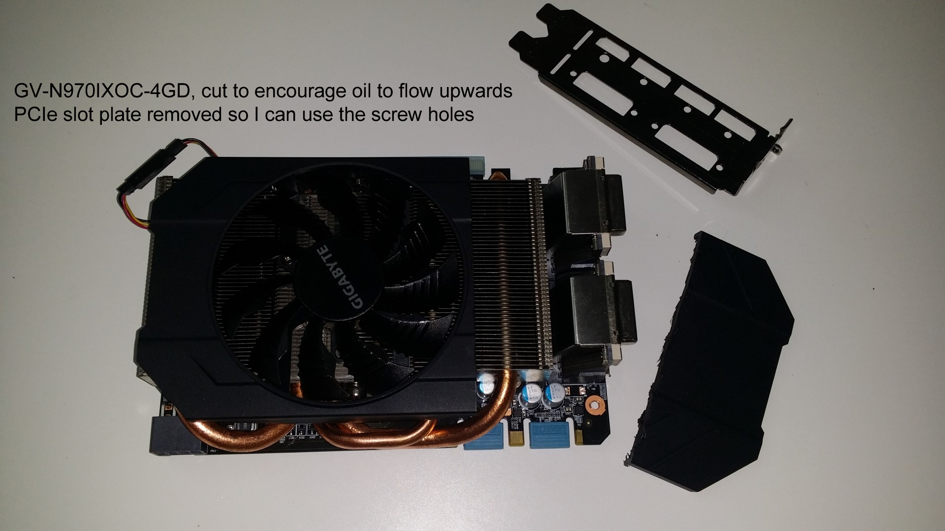
I want some decent performance while keeping heat generation low. I picked a Intel Core i7 4790S CPU because it has a lower TDP of 65W (versus 84W of the other models without the “S” at the end). The graphics card is a Gigabyte GV-N970IXOC-4GD because it is small (mini ITX form factor) and research suggested that the GTX 970 is substantially more power efficient in comparison to other GFX cards. The power supply is a Corsair CX600M because it was cheap, and it has 80+ Bronze efficiency rating. The estimated power usage is calculated to be well under 400W, so 600W will give me some headroom and allow me to power other stuff.
I have modified the PSU a bit to give it screw terminals. This is so that I can cut the cables shorter easily without repeatedly soldering to the PCB of the PSU. Every time I made a change to the PSU, I tested it after to make sure the voltages at all the nodes are correct (do this test before connecting anything so you don’t burn out your motherboard, CPU, GFX card, or hard drive). Be very careful because of the high voltages involved, and there’s a large capacitor that will store a charge even after being disconnected.
All of these are mounted on a tray I build using sheet polycarbonate, with holes cut out for all the IO ports. When you build a mineral oil submerged PC, always make sure the entire computer works before submerging it. If something doesn’t work, you need to get a replacement or refund. Mineral oil is hard to clean up so you don’t want to have to take it out of the oil to fix something. Building this tray allows me to arrange all the parts before submerging it. I also added some extra USB ports using a USB panel mount extension cable.
I have to be really careful with choosing materials. I’ve noted that some people who build mineral oil submerged computers experience no problems with any materials, while other people report that PVC will swell or harden. The PVC swelling is the cause of capacitors popping off circuit boards. Flexible vinyl tubing (also PVC) can become hard. A more detailed research indicates that capacitors on older motherboards has a rubber seal that is failing, causing hot electrolytic fluid inside to bulge, newer motherboards with “solid capacitors” should not fail. Vinyl tubing should not be operated at high temperatures. Rubber and neoprene must definitely be avoided as they will fail in mineral oil. PLA plastic (used by my 3D printer) can’t be used because PLA will warp even in hot water. ABS plastic (also used by my 3D printer) should be fine. Mineral oil is also used to clean many adhesives so I obviously need to be careful with that as well. I also researched possible sealants that can be used in mineral oil, Dow Corning 735 would work but I can’t find any to buy, Permatex 82180 can handle oils and high temperatures. I didn’t use any but I have some ready just in case.
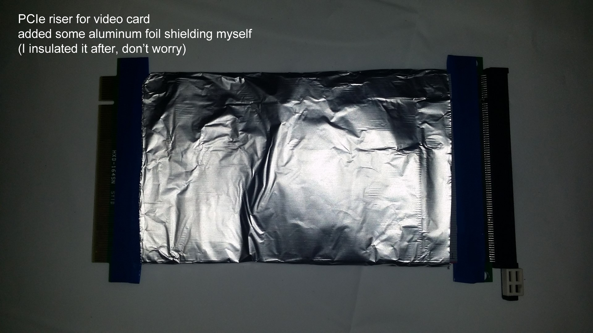
The GFX card isn’t connected directly to the PCI-E 16x slot, I used a riser cable so I can reorient it, because I have a thin fish tank. The riser cable is dirt cheap but doesn’t have shielding, so I used aluminum foil to add some shielding (the shielding is insulated after so the GFX card won’t short circuit). However, this is less necessary once the entire system is submerged, because the mineral oil will block much more electromagnetic interference than open air.
Other people who use 5 gallon tanks usually just put the entire PSU inside the tank without taking the case off, I have less room to work with, so I removed the casing on mine, and it looks better because you have more electronics to look at (it is still ugly compared to a $100 PSU). I keep the stock cooling fans on everything, they spin slowly in the oil, which looks awesome. I also had to resolder all the wires to make the cable short.
There is a cutout for the hard drive in the top cover. The SSD is mounted to a piece of plastic you can dip the drive into the oil but not let it completely drop to the bottom, and gives you something to grab on to when you need to remove the drive in case of emergencies. Two SATA extension cables are used for this but I really only need one drive, the second cable is available just in case, and I can use USB 3.0 for another drive.
I chose a 2.5” SSD because I thought they look nice and people immediately recognize what it is. I could’ve used a mSATA or M2 drive but then it would look boring, and hard to remove.
I made two circuit boards for this computer. One small circuit is mounted on the tank itself to act as a platform for various connectors, and it handles the power/HDD LEDs. The other circuit handles the Neopixel strip, temperature sensors (TMP36), and radiator (pump and fans). I used a AT90USB1286 microcontroller to run the circuit so I can read temperature data and give it LED/radiator commands using USB. A 12V wall wart powers the external circuitry and the motherboard signals are optoisolated to keep it safe.
(There is also a circuit that tricks the fan speed sensors into reporting speeds that are twice as fast as they are actually spinning, since they spin slowly in liquid as opposed to air. this is unnecessary but I was paranoid that the motherboard would freak out)
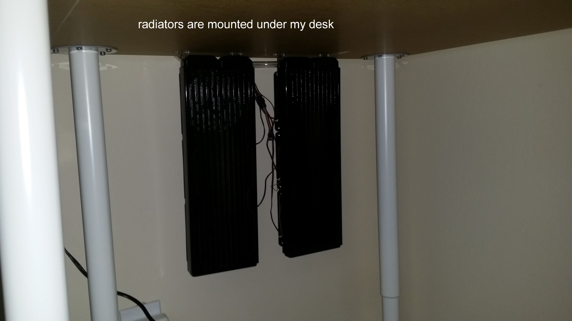
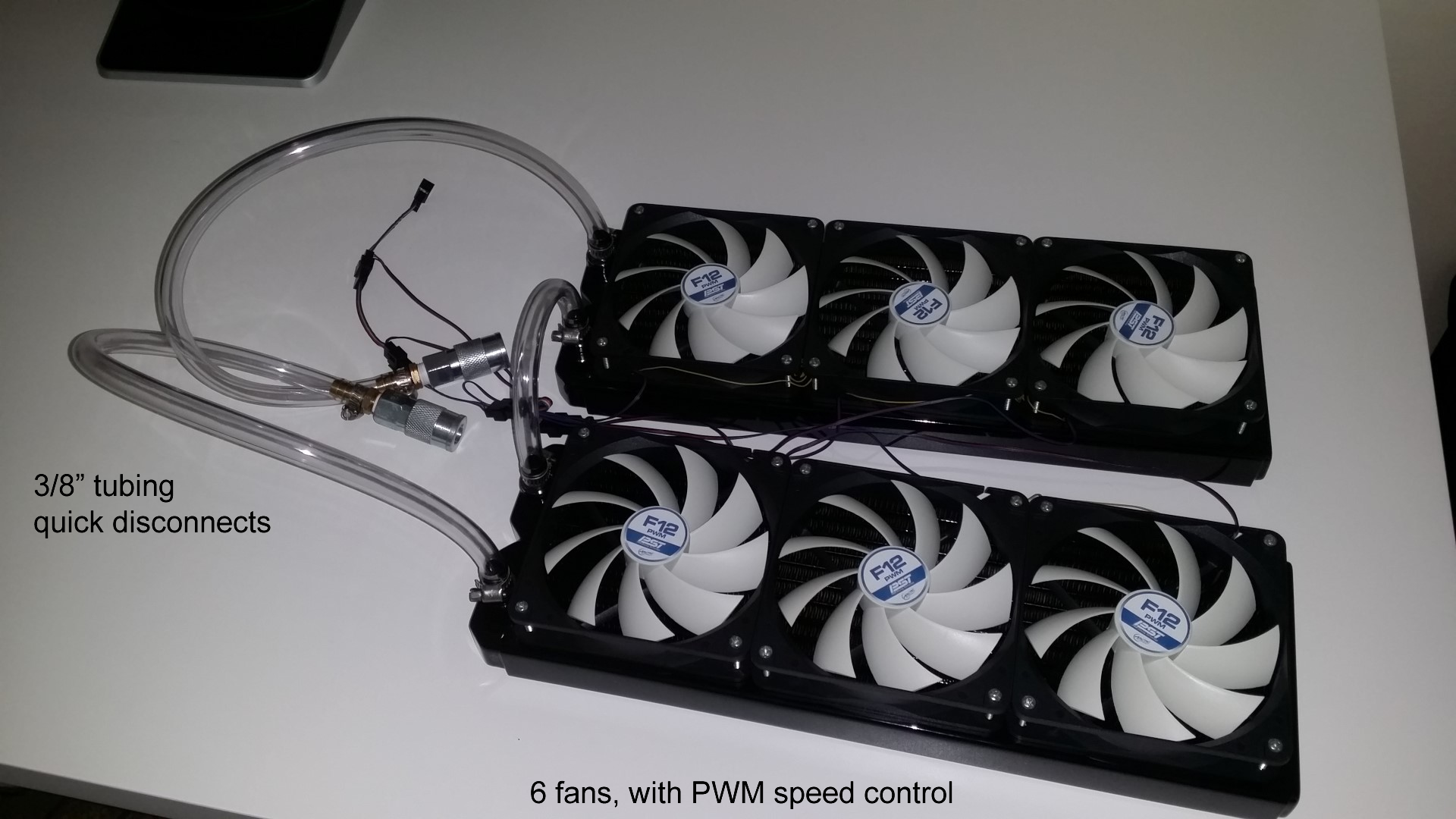
I used a pump capable of 4 L/min, it’s advertised to be brushless, submersible, and able to handle all sorts of chemicals. According to my research, this is almost 10x more flow than a traditional closed-loop CPU water cooler. The pump is dangled inside the tank, which should dampen any sound. The radiator is a long one designed to fit several 120mm PC case fans. I chose some cheap fans with hydro bearings and PWM speed control. I felt that these components gave me a efficient low noise long life setup.
During my research, I’ve seen systems built without radiators at all, even with a discrete graphics card. But I’ve also seen people use radiators with 4 fans, or even 9 fans. Without knowing the full specifications of their system, it’s really hard to judge how powerful I need to make my radiator. Hence why I designed the computer in a way that I can add another radiator easily, the tubing is already there with quick disconnects, I just need to build another radiator and connect it. My microcontroller can handle whether or not it is powered, to give me the best balance between noise and heat.
According to research, even a high powered system under stress test will take hours to heat up to dangerous temperatures without a radiator. I am confident that my radiator setup can handle my expected amount of gaming. I won’t be doing too much data crunching and rendering, but I want to do them fast when I need to. I mainly want to open large and complex 3D CAD models smoothly, and slice them at high polygon for 3D printing (which my current laptop has trouble doing).
Testing
These results are not scientific in any way, but they will give you an idea of the temperatures to expect with a setup similar to mine.
12/15/2014:
The temperature sensors appear to not work, so the oil temperature was taken with my multimeter, a thermocouple, and a notebook, so sorry, no pretty graphs until I fix the temperature sensors.
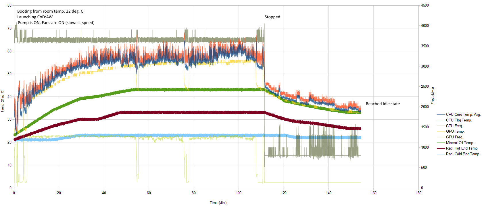
I turned on the computer at about 7:20PM, room temperature was around 22 degrees C and the mineral oil was at 22 deg C. Once Windows booted, CPU was at about 30 deg C. Remember that the oil temperature will not change drastically. The pump is turned on and the fan speed is set to minimal. The CPU is allowed to run at maximum frequency on all 4 cores. The test begins.
I started playing CoD:AW at around 7:30PM, and the temperature started to steadily climb on everything. At 8:40PM, the temperature of the mineral oil reached 44 deg C and stayed that way until I stopped playing at 9:40PM. The maximum CPU temperature reached during the session was 60 deg C, and the maximum GPU temperature reached during the session was 57 deg C. I think I am pushing the system pretty hard, I did notice some stuttering in the game so I think it is a heavy load.
When I stopped playing, the temperature detected near the radiator’s intake is about 29 deg C, and 22 deg near the outlet.
Idle temperatures with Windows 8.1 running at 800 MHz on all 4 cores, CPU, GPU, and mineral oil, are all about 35 deg C. It reached this state at about 10:15PM. There are two zones on the bottom that don’t get any oil flow, they were much colder at around 28 deg C.
Subjectively speaking, I think these are perfectly safe temperatures so far.
Sensor Failure
I think I know why my sensors stopped working. They are mounted close to switching DC/DC converters. I looked at the signal with my o’scope and it looks like there is a large periodic noise being coupled into the sensor readings. When the computer is off, the noise goes away.
The noise could be coupled from the DC/DC switching circuitry, or because the cables are also near the same cables used by the PSU.
I really don’t want to take the computer out just to re-position these sensors, which are mounted very securely.
12/15/2014:
Another similar test as the one yesterday, except the oil outlet has been moved upwards slightly to make it easier for the pump to start.
just more ranting by me for the sake of journaling my thoughts:
This project is very stressful. The parts are expensive and sensitive. I wasn’t able to pre-plan anything until after buying the parts. The only useful drawing you can get is dimensions of a mATX motherboard, but I couldn’t know how to cut the holes for the rear IOs of the motherboard or for the GFX card. I didn’t even know I had to put in my GFX card in at an angle because the fish tank was so small (only rough dimensions of the fish tank was known, not enough to model). So this meant that there’s a lot of uncertainty and risk during this project and you might have wasted several hundred dollars (after voiding warranties) and the things might not even fit.
It did boot perfectly with no issues on the very first try, which was a huge relief. If you think “I know that feel bro”, no you don’t… You didn’t take a 600W PSU out of its casing, and solder wires to it, including the AC mains, on your very first PC build ever. All warranty was voided at this point already.
Upgrading would be annoying because everything would be dripping in oil when I take parts out. So I decided to go with late life last generation (DDR3 RAM and H97M chipset) parts instead of early life new generation (DDR4 RAM and X99 chipset).
Using a mini ITX motherboard would have been easier but I really wanted 4 RAM slots. Using a SFX sized PSU might have also saved some space but I didn’t want to spend the extra money.
If you want to build one yourself but don’t want to put in as much effort as I did, then you can try dipping a mini PC in a smaller tank. If I were to do this again, I might consider starting off with something like a Zotac Zbox or Gigabyte BRIX (these two both can still game very well). Or… well basically you can just get any motherboard with integrated graphics if you don’t want heavy gaming, and get an appropriate sized tank. A tiny media player would work too, but it won’t have slow spinning fans, so you should add more decorations and bubbles and plants if it looks too boring.
I also considered submerging my PS4 but it has IOs on both sides, the PCB is very tall, and the optical drive must be kept dry. It definitely could be done but I didn’t want to do this and still spend money on a boring computer.
On the internet, the vast majority of PC builders don’t actually know much. This lead to some of my questions being completely ignored, and thus I had to use my electrical engineering intuition. Also it means that most products are designed to favor easy-of-use and wider compatibility instead of being optimized for my build. Gigabyte even color coded their 8 pin ATX cable wrong (red was ground, black is also ground, usually red is +5V in ATX cables).
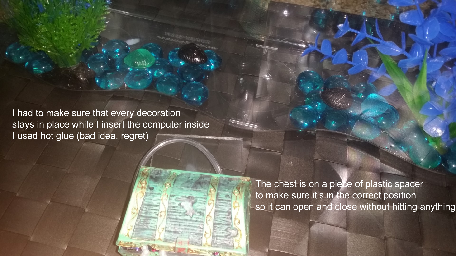
Acrylic is very easy to scratch, be super careful. Also avoid using hot glue, the hairy strands are hard to clean up.
The Neopixel strip has 51 LEDs, at half brightness in the rainbow pattern, my circuit uses 170 mA. Add the pump and low fan speeds (20% PWM duty cycle), about 800 mA used. If all 6 fans go full blast, 2000+ mA. My 12V wall wart (separate from the main PSU) overheated after 30 minutes at 2000 mA.
All circuitry is done on perfboard without any planning, so sorry, I can’t share any diagrams because I never drew any.
The radiators I purchased SUCKS. The threading for hose barbs were really poor. It also uses sheet metal screws and simple sheet metal holes, once you mount your fans in, it is almost impossible to get those screws back out. I would avoid “Black Ice X-Flow Pro” in the future, and find one that has real threading for mounting fans.
I used pneumatic quick disconnects to make hooking up the plumbing easier. I have no idea what they use to make a seal. If they use rubber or neoprene, then the mineral oil might damage it. McMaster-Carr has some that uses nitrile to make the seal, which I think is safe in mineral oil. I am hoping the ones I used, from Home Depot, are safe.
This thing looks soooooo awesome!!!!! The temperature gradient in the oil causes light diffraction, like how the air becomes wavey coming off a hot pavement. The bubbles and Neopixels are fantastic and the light is scattered on the bottom, making a rainbow ring around the edges of the tank. It is a work of art.
Fun fact: 2 years ago, I wrote a report on a project like this for my thermodynamics class while at UW.
Update March 2015
This computer is running 24/7, and has been since its construction. There appears to be a problem with the USB port power. I find it difficult to get USB 3.0 external HDDs to work now, and it is unable to provide charge current to my smartphone. Sometimes, the motherboard would not boot, citing a USB port has detected over-current. This did not occur when the computer was new, the USB port reliability slightly degraded over time. Sometimes something won’t work, and I can get it to work by unplugging the PSU for a while.
Although it sounds like a power supply issue, I measured the 5V bus and didn’t detect anything unusual. I think the problem is on the motherboard USB power management circuitry, and not the PSU itself. If it was the PSU’s problem, then my SSD wouldn’t work and thus my PC should have basically been dead.
I got tired of not being able to use my USB ports so I decided to purchase a massive 7 port hub with a 12V 5A capable external supply, which translates into roughly 10.8A worth of current at 5V if I assume 90% efficiency. This solved the problem completely.