I’ve had some fun with photogrammetry recently and wanted to try out other techniques for 3D scanning. I’ve actually sort of accomplished S.L.A.M. during a hackathon using the PlayStation 4 camera and the Xbox One Kinect already, but I wanted something portable! With the new Raspberry Pi 4 debuting this year, I can finally accomplish this… sort of…
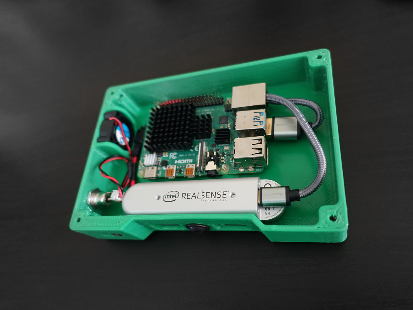
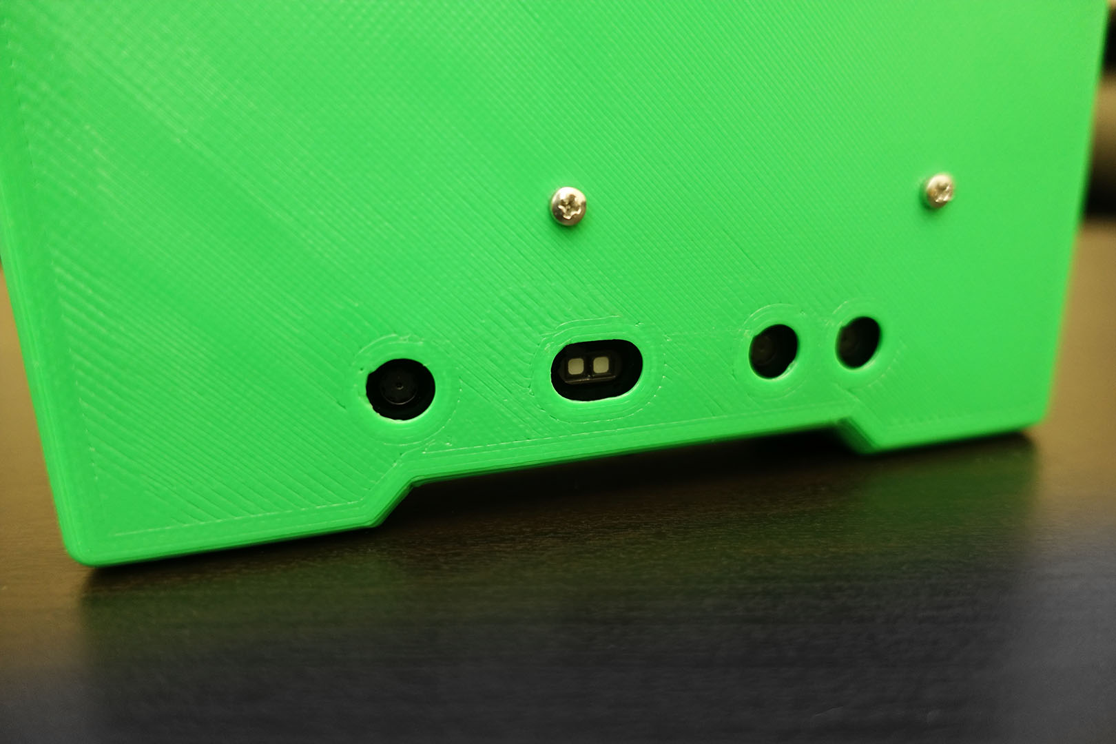
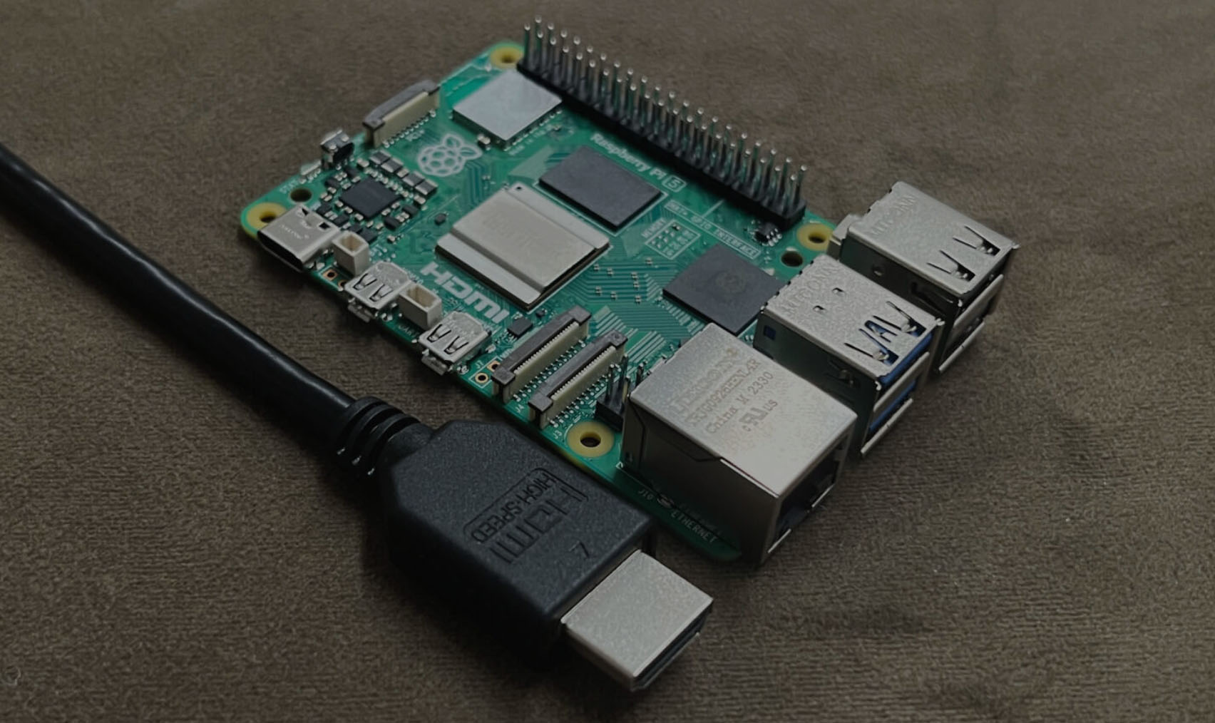
Inside this 3D printed case is a Raspberry Pi 4 and a Intel RealSense D415 camera. The D415 is a depth sensing camera, using active stereo IR cameras and an internal processor to generate depth map data. It also has an ordinary RGB camera as well. That’s a lot of data to push through, hence why the newest Raspberry Pi 4 this year is important, because it has USB 3.0 ports that can handle all that data. (the ARM processor inside also has a faster architecture than before)
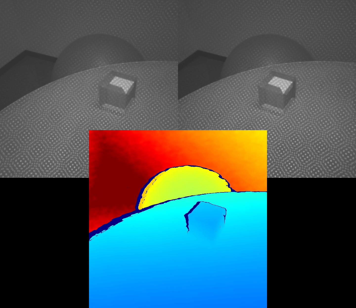
How does the depth sensing work? Have you read my post on photogrammetry yet? There are some overlaps between the techniques. There are two IR cameras spaced apart, and it can see two very similar but shifted images. The processor finds interesting points (i.e. feature extraction) in the two images that are similar and match them up, the coordinates of these points can be used to calculate the 3D coordinates of those points relative to the cameras (i.e. binocular disparity).
Why infrared?
When there are not a lot of interesting features for the processor to look at, the depth sensing will get bad results. Flat and texture-less objects are hard to 3D scan for this reason. To solve this, the RealSense camera has an infrared dot projector, which shines a pattern of dots onto the surface, so that even if it’s texture-less, the dots become the texture. This makes it easier for the processor to calculate more depth data points. We want to use infrared and not ordinary light simply because we don’t want to annoy human beings.
A similar technology is already used in the latest iPhone with Face ID.
The Raspberry Pi 4 is running Raspbian Buster and has a program called RTAB-Map (Real-Time Appearance-Based Mapping) installed. This amazing piece of open source software is intended for robotics applications. It can perform S.L.A.M. (simultaneous localization and mapping), so a robot is able to map its environment in 3D, and also locate itself within that environment in 3D. When you connect it to a RGB-D (the D is for depth) camera like the D415, it will use the depth data to find the walls and obstacles for the robot. For the location, it uses the same techniques as we’ve covered before, extracting features in the RGB image, and then computing the relative movement of the robot based on how the extracted features are moving in subsequent image frames.
Did you pay attention to my video, the part where I walk down a hallway? Did you notice how I picked a location with many posters on the walls? The video below is the same clip but slowed down, pay attention to those green and yellow dots, those are extracted features that are being tracked.
RTAB-Map would not have been able to track me if those posters were not there. I picked that hallway specifically for filming because I knew the posters there would provide RTAB-Map more features to track. If you showed RTAB-Map a few white walls, it would get lost since there’s not enough image features to track (did you notice there were no dots on the walls?).
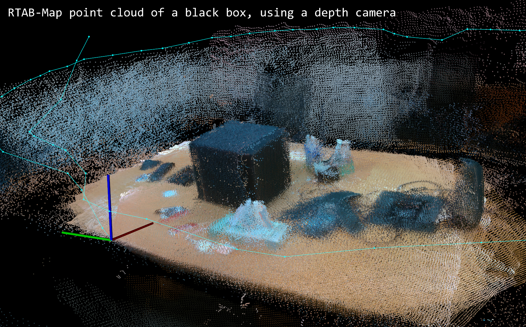
With RTAB-Map, we can now place a point cloud of an object in 3D space because we have a depth sensing camera and we are tracking the 3D coordinates and 3D orientation of that camera.
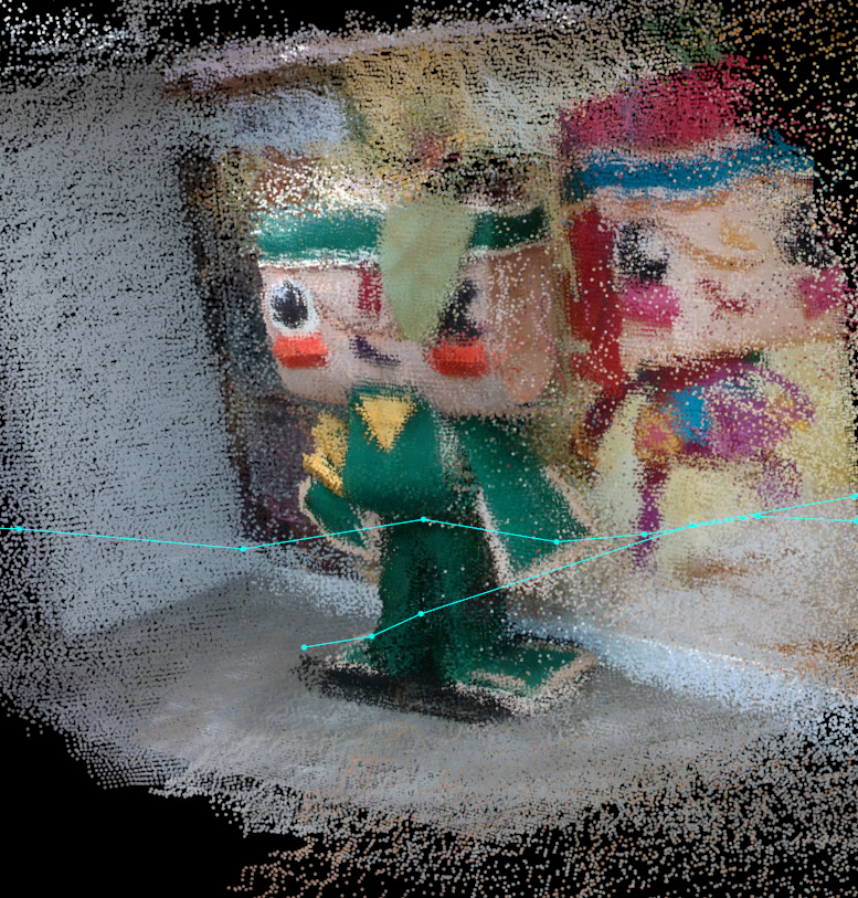
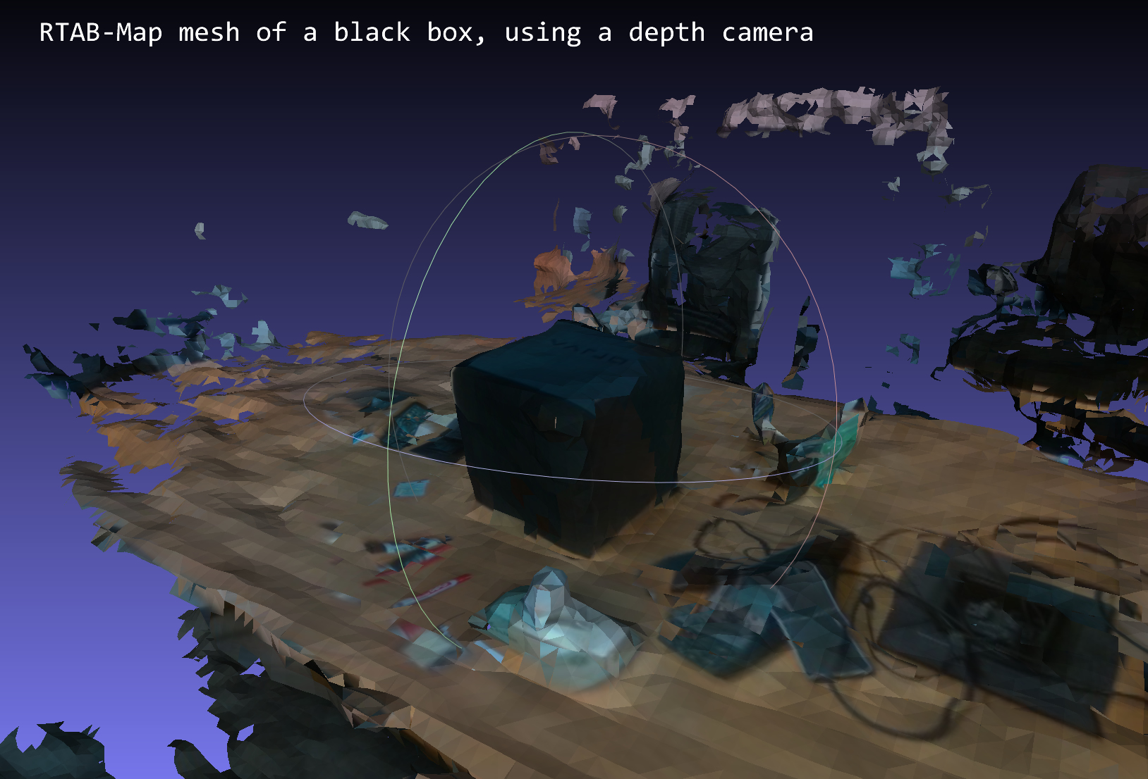
This is how it becomes a 3D scanner. RTAB-Map also has the ability to stick that point cloud into a mesh for you, and also give it texture! Amazing!
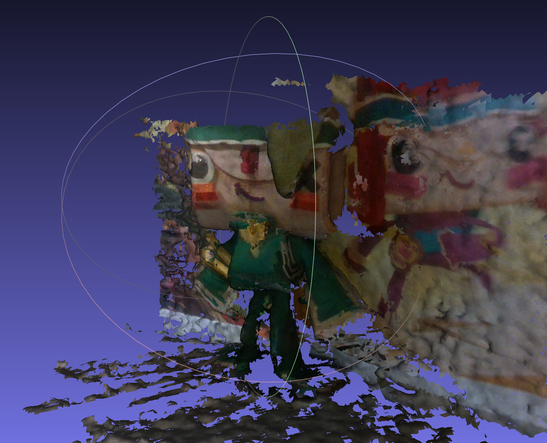
Well the 3D scan results I got from this project absolutely cannot beat the quality of a photogrammetry scan. Due to the amount of noise in the depth map and the lower resolution of the cameras, the resulting surface quality is poor. However, this technique could succeed where photogrammetry fails. Remember that photogrammetry will fail on texture-less objects! Here’s a comparison between photogrammetry vs depth sensing camera:
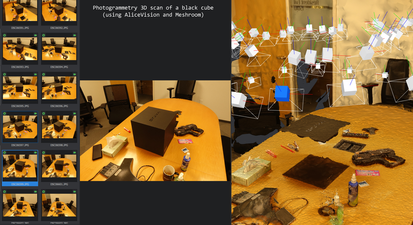
Yep… completely failed to detect that there was a box there…
RTAB-Map is a S.L.A.M. software sandbox, not exactly 3D scanning software. What it does is actually combine many open source libraries, and let you choose which one is being used for each step in the processing. For example, for the feature extraction, it offers 11 different techniques! 4 different methods for feature quantization, 4 different solvers for its graph optimization, about 10 different odometry implementations… This application is definitely a great tool in the hands of a researcher, as well as robot builder. It also means that the results from this scanner can be improved upon if I knew how to play with all the different settings more.
Other Potential Methods
The Xbox One Kinect uses a small time-of-flight camera. It has a low resolution of only about 320×240 (where as Intel has 1280×720), but since it doesn’t need to use binocular disparity, the data is MUCH cleaner. Too bad I can’t get this sensor standalone, and the Kinect is simply too big and power hungry.
Intel also sells some depth cameras that uses structured light. This means projecting lines onto an object and the camera analyzes the curvature of the lines in order to generate a 3D model. This works great at short ranges, and is already wide spread in any computer that can use 3D facial recognition for authentication (e.g. Windows Hello). I wanted to play with something long range since I am also interested in room-scanning, and robotics.
If you looked for a “Raspberry Pi 3D scanner” right now, the majority of them are either automated photogrammetry rigs (either with multiple cameras or with a 3 axis turn-table), or a structured-light 3D scanner built with a projector (sometimes lasers). I believe my own implementation here is kind of a first in the Raspberry Pi world, simply because the USB throughput and processing horse power isn’t available in the older Raspberry Pis, only the newest Pi 4 has the capabilities required, and they just released this year.
What I really want is for AliceVision/Meshroom to be able to take RGB-D data instead of just RGB data. This way, we can achieve much higher quality 3D meshes, and use the depth data to fill in areas where photogrammetry fails to extract feature points.
Wanna Try?
This seems like a simple project, right? Plug a $150 camera into a Raspberry Pi and install some software… sounds easy? Well, I made it easy for you…
The installation is actually quite challenging if you are starting from scratch. You have to build several pieces of software from scratch. Since Raspbian Buster is so new, there’s a lot of incompatibility and dependency issues. I have made this easier by wrapping all of the installation into a single installer script. The installer script will apply patches to certain files to prevent build errors. The other great thing is that I’ve made the installer very robust, so you can pause it and continue from where you’ve left off, which is nice because it takes several hours. You can trust my installer script because the source code is available and the actual software is getting pulled from many github repos.
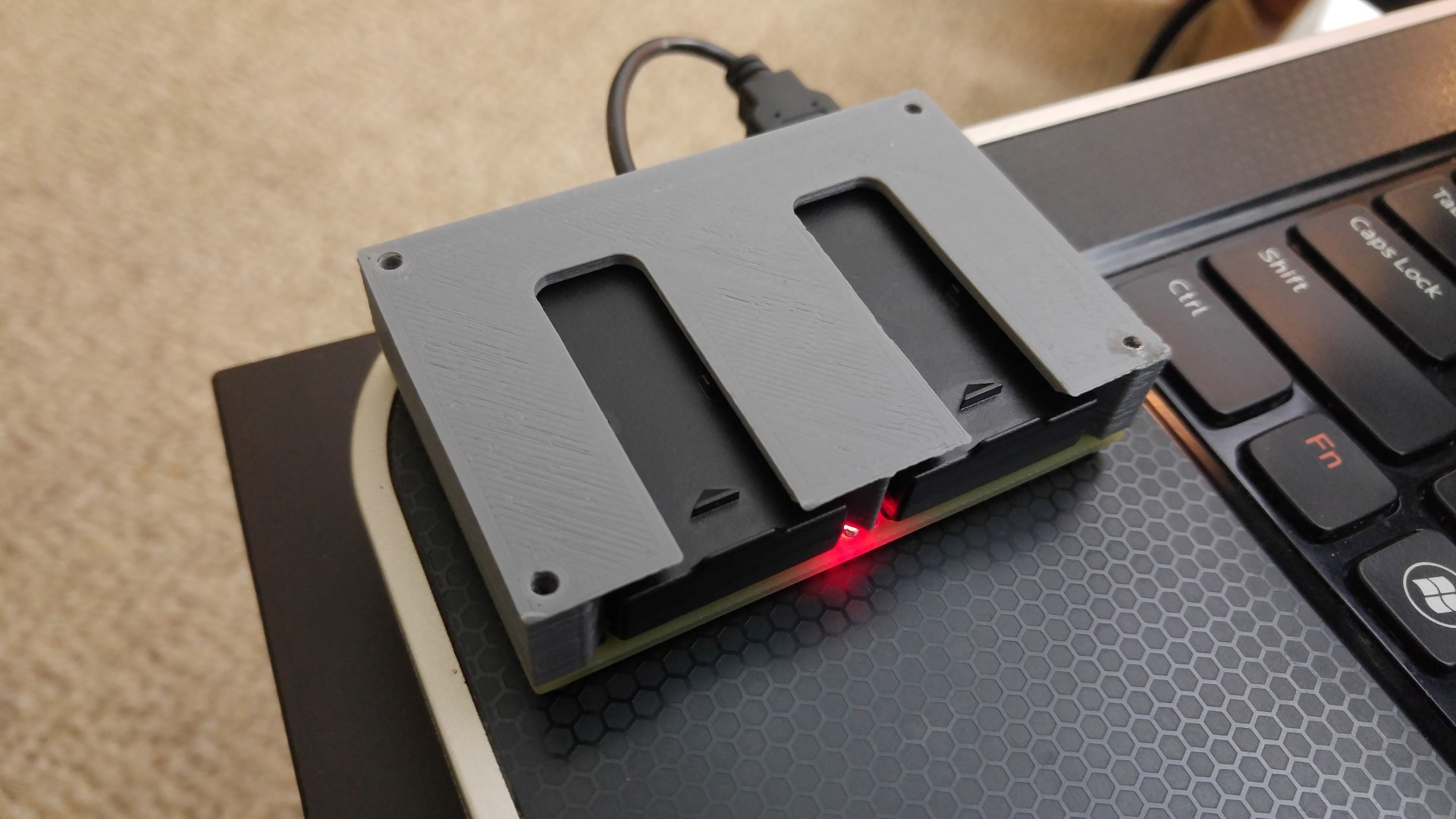
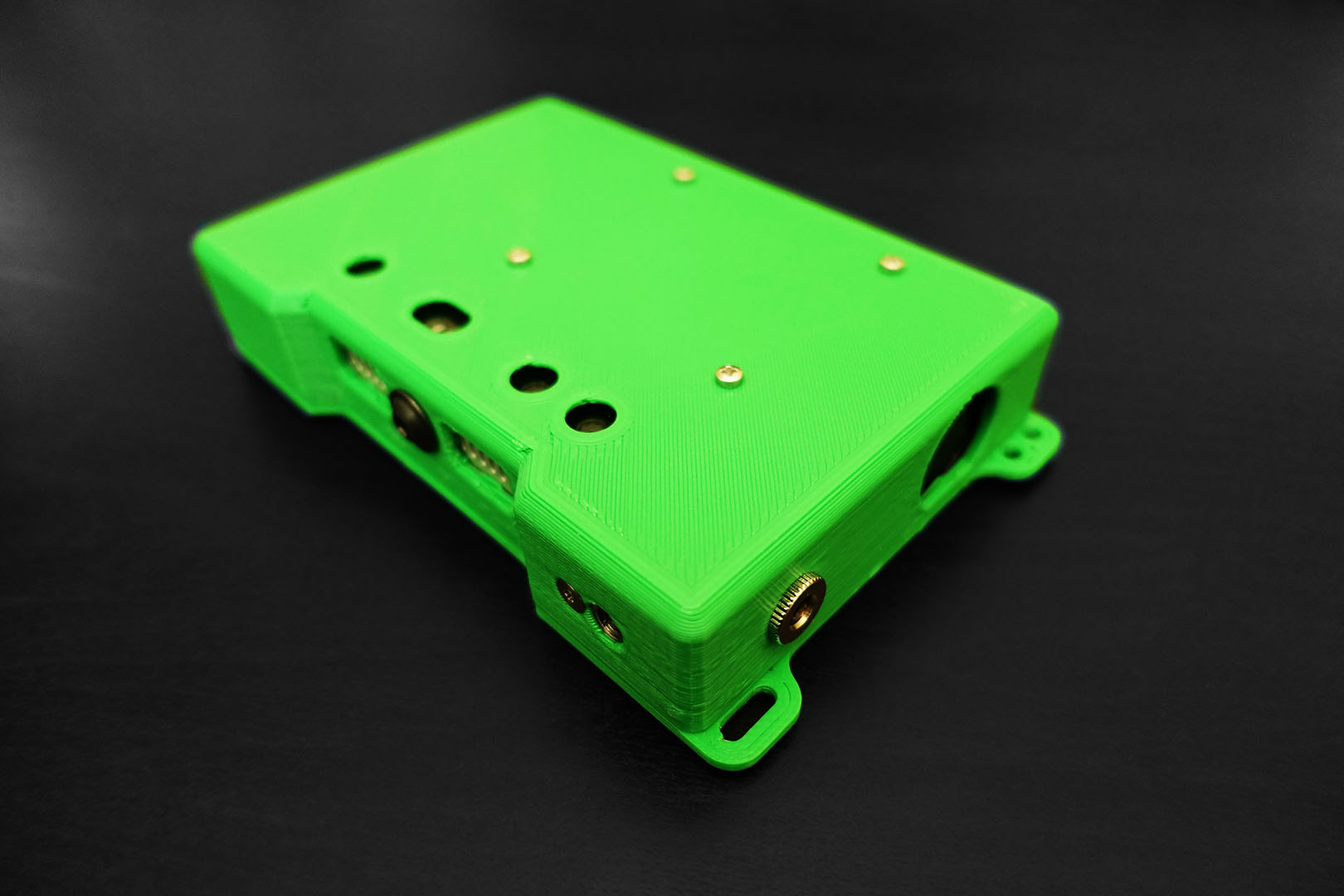
The case for this project is 3D printed. The 3D model and CAD files are also open source.
All of this is up on my github account: https://github.com/frank26080115/HandHeld3DScanner
And for fun, here’s a page I wrote to track some of the problems I encountered during the software builds: https://eleccelerator.com/wiki/index.php?title=Raspbian_Buster_ROS_RealSense
Other Fun Details
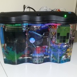
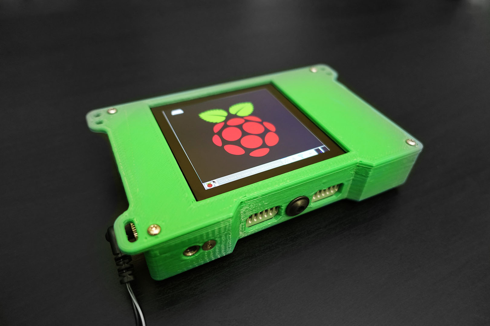
The touch screen is a HyperPixel 4 Square Edition, with a resolution of 720×720. I have provided 3D models for both the square and rectangular versions.
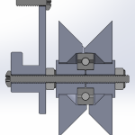
The cooling fan and heatsink (a monstrous 30mm heatsink is stuck to the CPU) is very essential to this project. RTAB-Map works better when you have a better frame rate, so you never want to have your CPU reach thermal throttling temperatures. The combination of the fan and the heatsink keeps the CPU below 60°C.
The power supply is a USB power bank capable of 3A per port. This project is very power hungry and any off-the-shelf cables will start to exhibit unacceptable voltage drops. Even if the power supply is supplying 5.2V, I found that only 4.6V would reach the Raspberry Pi when under full load. I actually had to make a dedicated cable for this project out of 14 AWG wiring to reduce the cable’s resistance, since the CPU will throttle itself when it detects an undervoltage alert from the PMIC.
The case also has a tripod screw hole. It’s off-center so it’s not exactly great for tripods… but it’s great for me to attach that POV camera I used to shoot that film with. All the other holes on the lid of the case are meant for hand straps and lanyards. The slot hole is meant for velcro straps, if you need to secure the power cable.