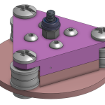
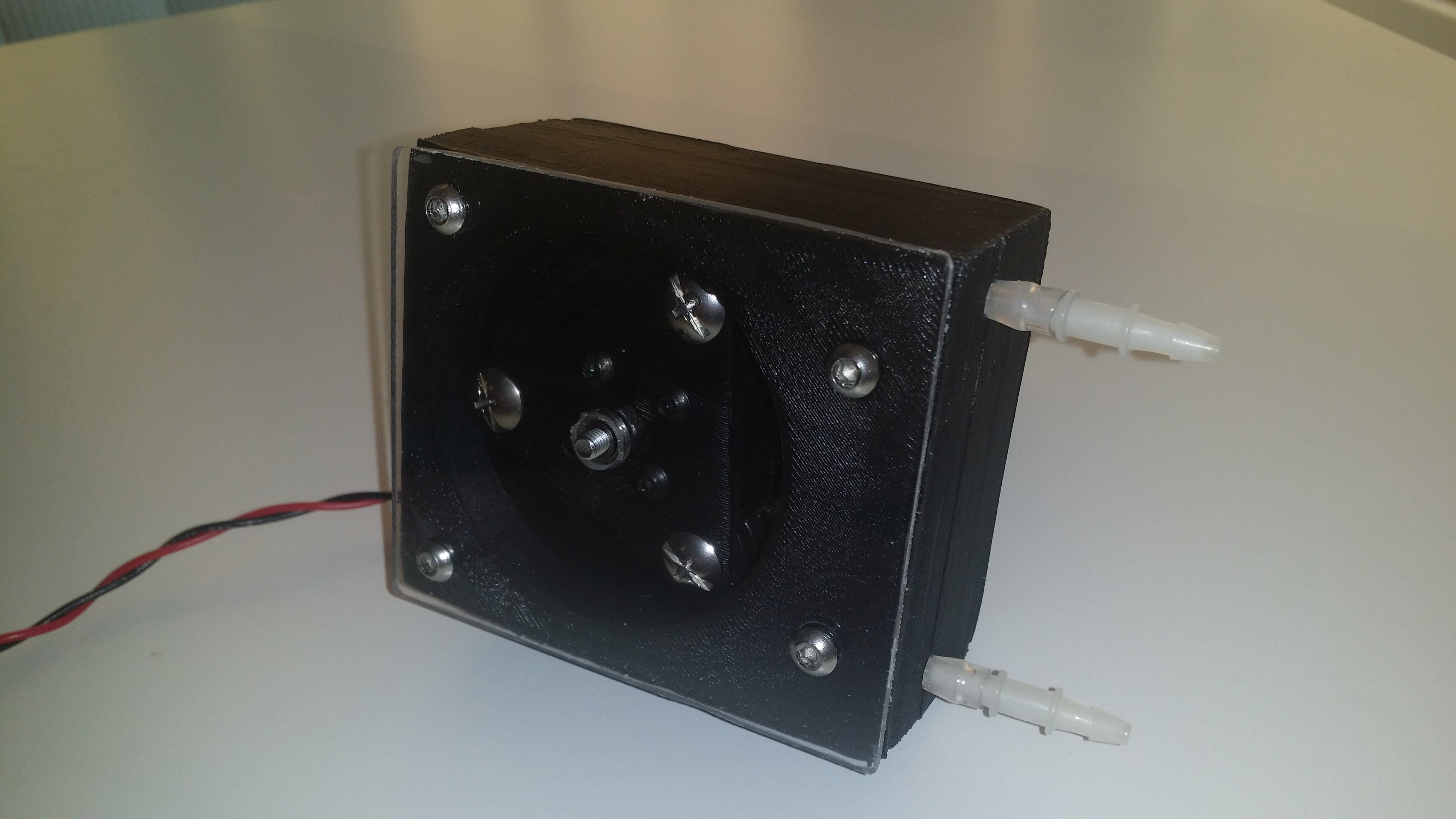
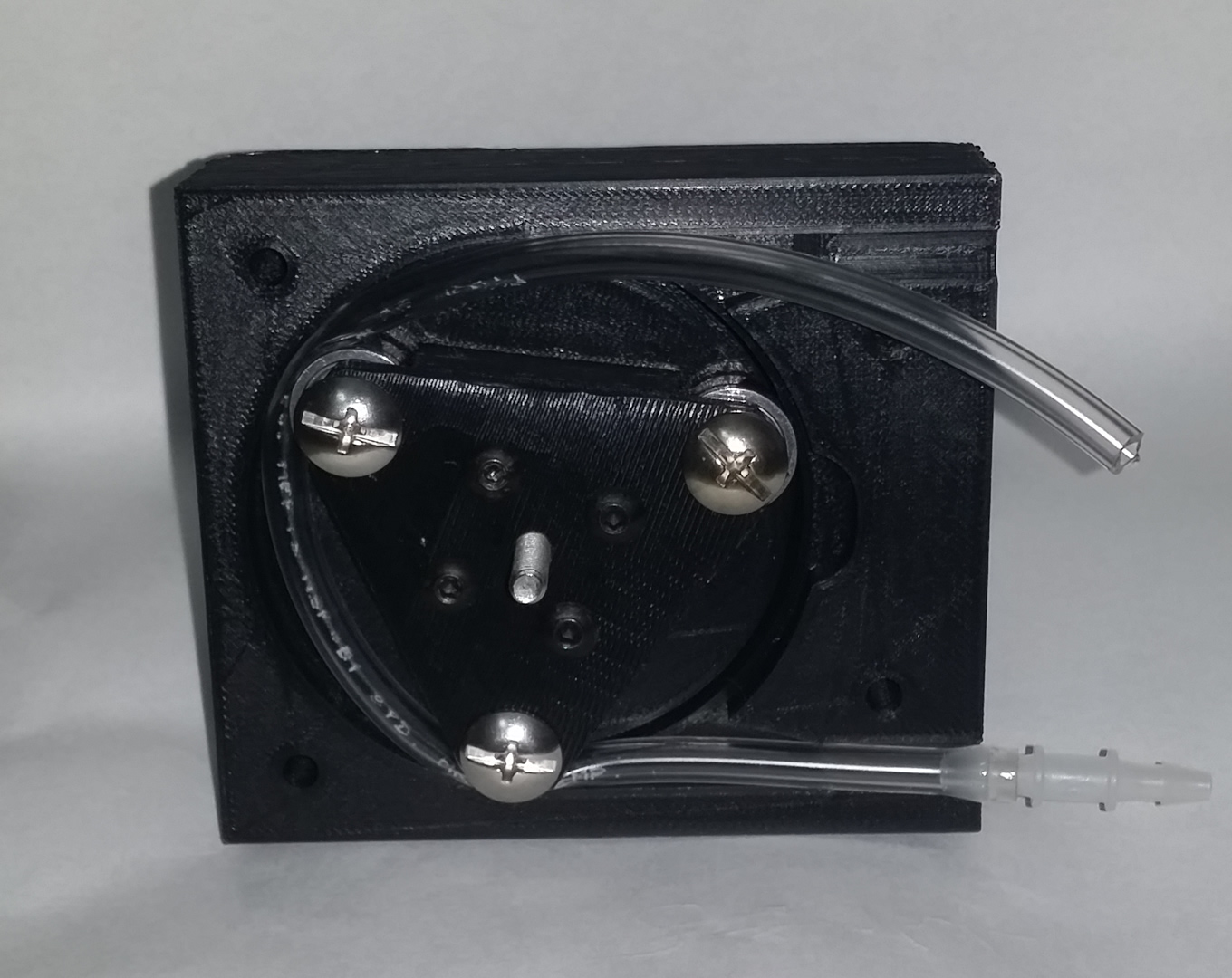
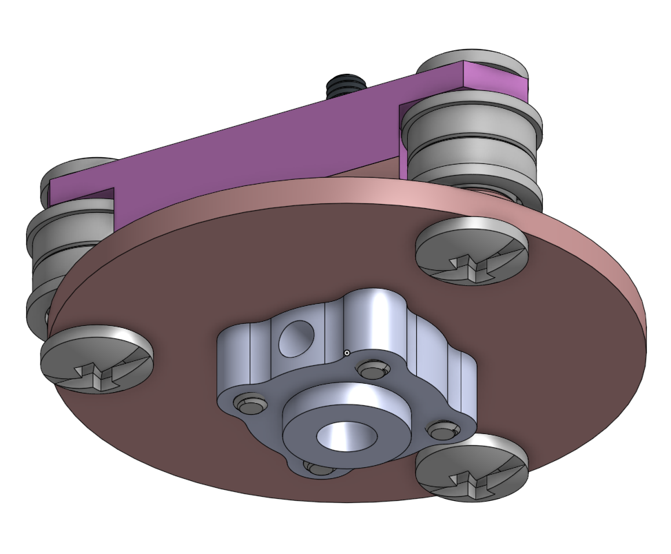
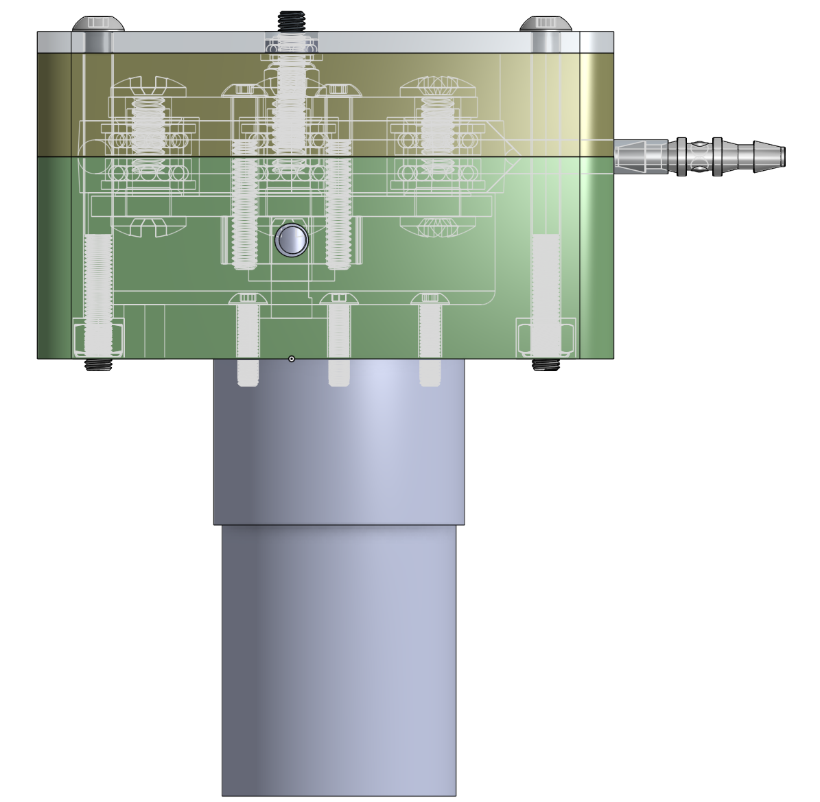
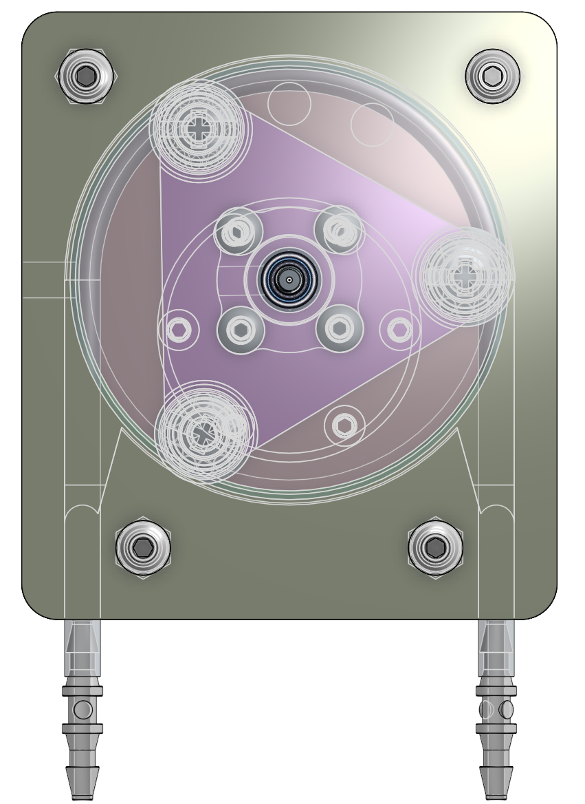
I 3D printed a very durable peristaltic pump. It is capable of pumping very thick liquids at as much pressure as the tube can handle. It is durable because it is printed at 100% infill at high thicknesses and uses steel ball bearings. It is capable of such strength because it is using a massive 12V DC brushed motor that has a 150:1 gear ratio metal gear box, which means several kilograms of torque.
For design files and more details, please continue reading.
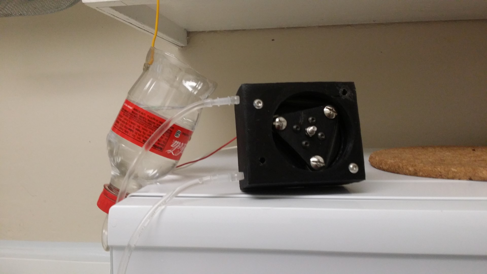
Purpose:
My grandfather (living in China) has esophagus cancer and needs to eat through a feeding tube. The liquid food he needs to eat is quite thick, and it is usually pushed through a syringe. But this takes a lot of strength and me, my dad, and my uncle are the ones doing this. But I live in the USA, my dad lives in Canada, and my uncle is in China and don’t have any more days off, meaning my grandmother needs to feed my grandfather. My grandmother does not have the strength to push the thick liquid through the syringe. So hence I decided to build a pump for them.

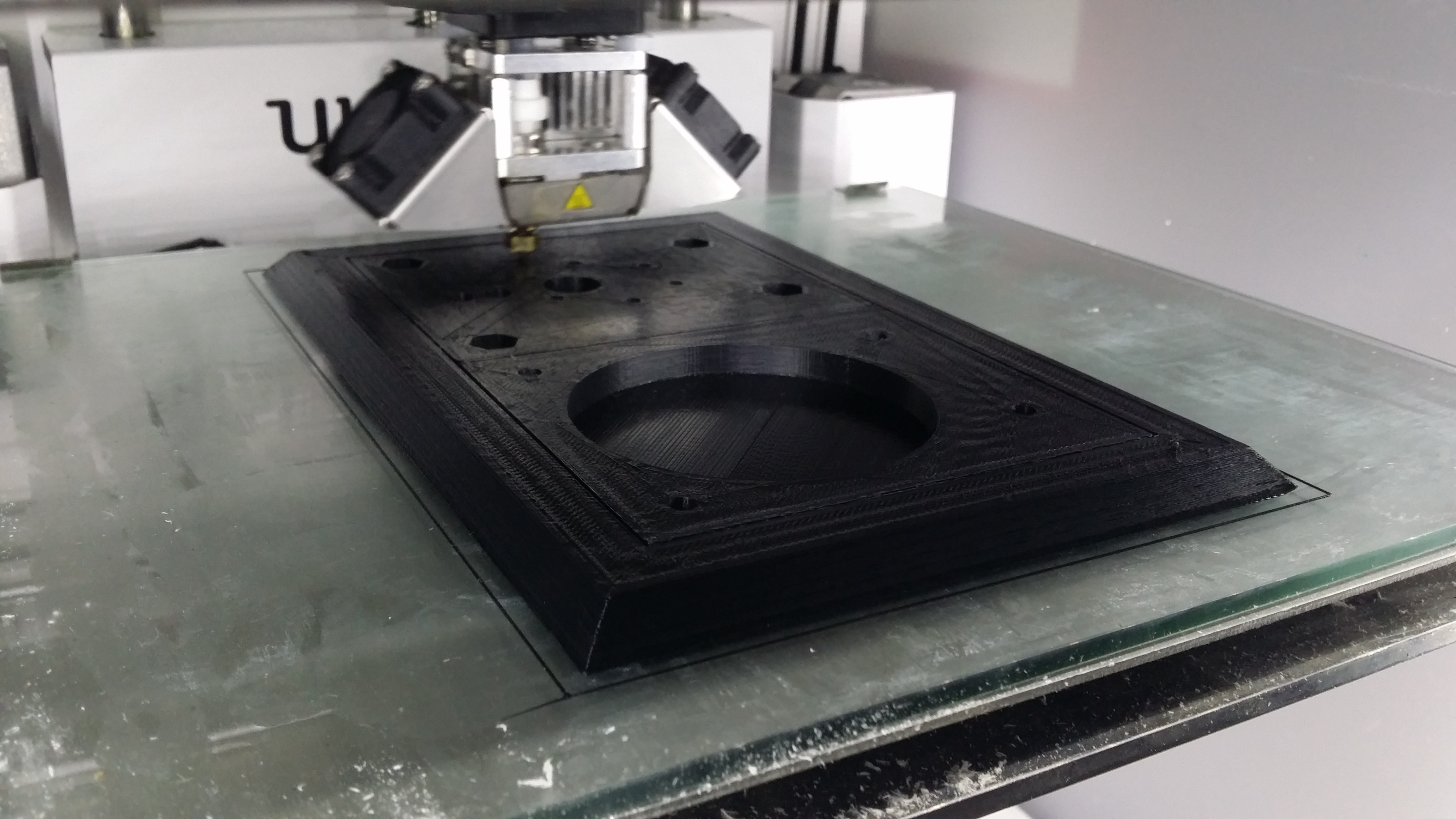
3D Print:
The biggest challenge here is caused by the fact that the plastic is printed hot and then cools during the print. This means there’s some shrinkage, which causes bed adhesion problems (corners lifting during print, my new solution click here) and dimensional inaccuracies. The print also takes a long time. This design and requirements cannot be printed at a 3D Hub service. Dimensions may need to be readjusted to achieve an airtight seal in the tube. Another trick is to superglue tape inside the housing to adjust the pump’s diameter.
The files I will provide will be the publicly shared Onshape documents here, so you can edit the dimensions easily. Remember, STL files suck for sharing designs, do not ask me to share STL files.
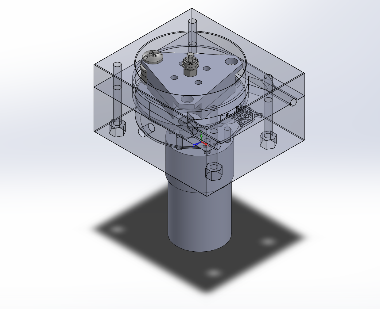
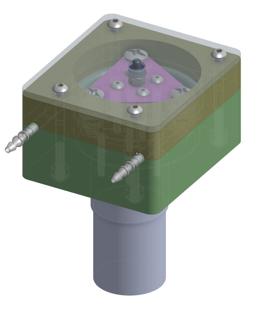
Actually, I originally designed this completely in SolidWorks, but I wanted to share a file with dimensions that can be edited using a free tool, and Onshape is free, so I decided to use Onshape to exactly replicate the model.
Mechanical Parts:
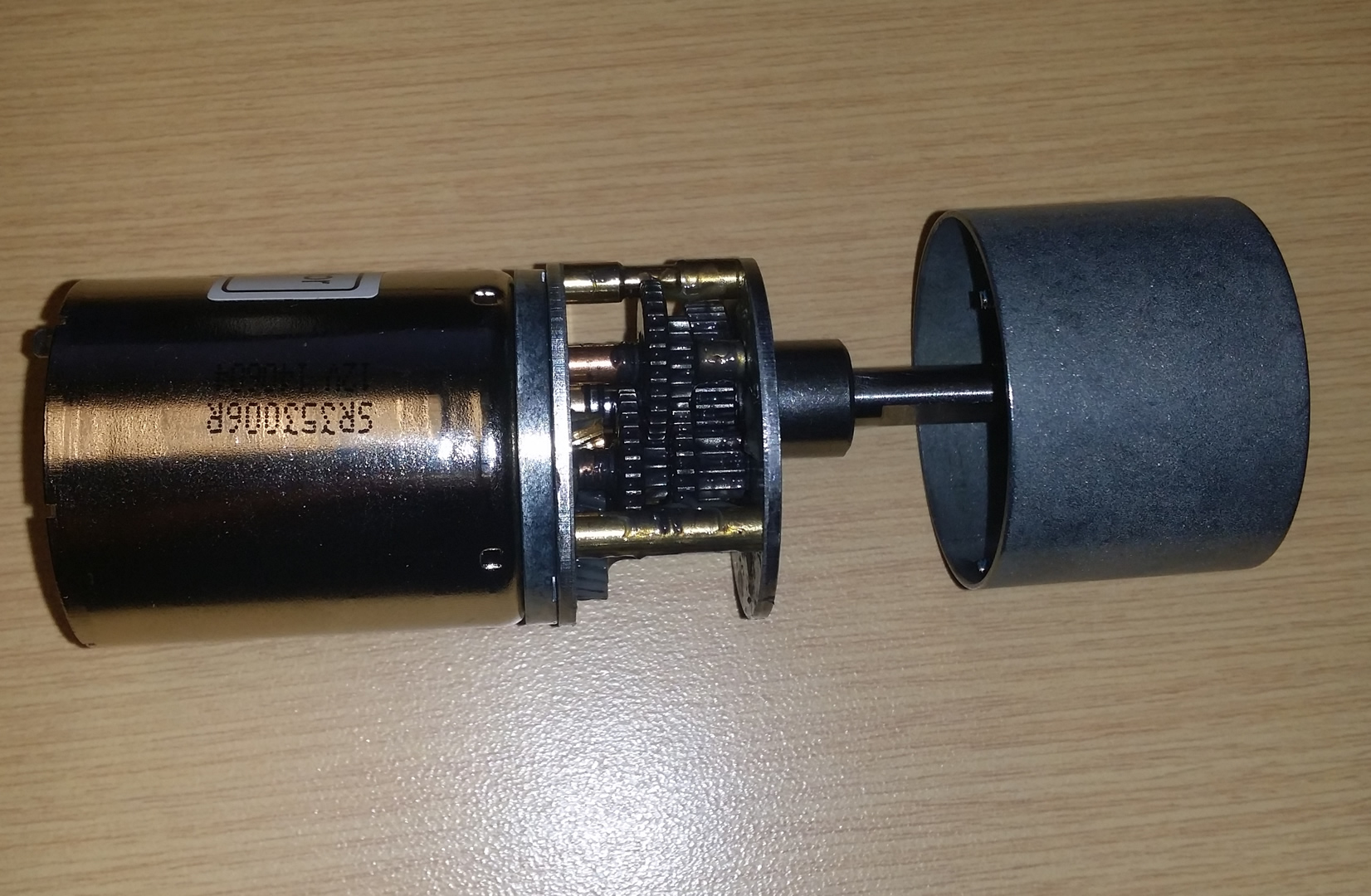
- DC brushed motor, with precision spur gear gearbox, 6V-12V operating voltage, 6mm D shaft, part 638222 on Servo City or item number 1107 on Pololu
- Actobotics brand 0.770″ set screw hub for 6mm shafts, part 545576 on Servo City
- very flexible very soft tubing, 5mm OD, 3mm ID, FDA approved
- barbed couplings for the tubing mentioned above, these hold the tube in place, FDA approved, 1/8 inch diameter is acceptable as well
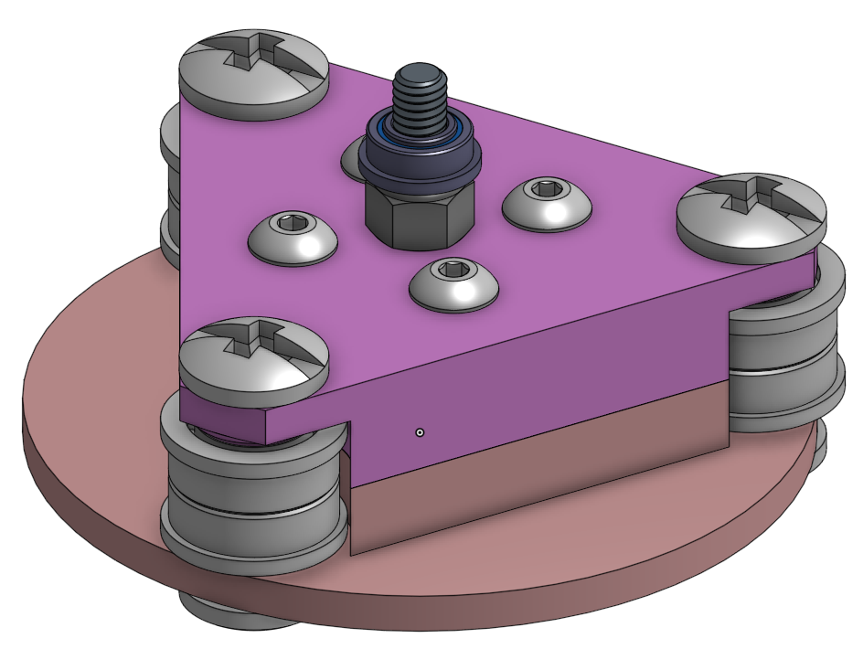
- 6x steel ball bearing, double shielded, 1/4 inch ID, 1/2 inch OD, used as the rollers
- binding post, 1/4″ barrel diameter, #10 screw, 5/8 to 3/4 inch length, used as axles for the bearings
- 4x #6-32 machine screw 1 inch long, holds the rotor to the hub
- 6x M3 machine screw 0.5mm pitch 12mm long, holds the motor to the pump housing
- 4x M4 nylon locking nut, to hold the pump housing together
- 4x M4 machine screw 50mm long, to hold the pump housing together
- 1x M4 screw with hex head cap 20mm long fully threaded, optional, used as an axle on the rotor, if you wanted to add a dust shield with another bearing
- 1x M4 nylon locking nut, optional, to hold hex head cap screw mentioned above
- 1x steel ball bearing, double shielded, flanged, with extended inner ring, 5/32 inch ID, 5/16 inch OD, optional, if you wanted to add a dust shield with another bearing
- 1/8 inch thick clear polycarbonate sheet, optional, cut and drill into a dust shield
- optionally use Loctite on the screws without nylon locking nuts
The Control Circuit:
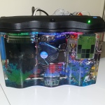
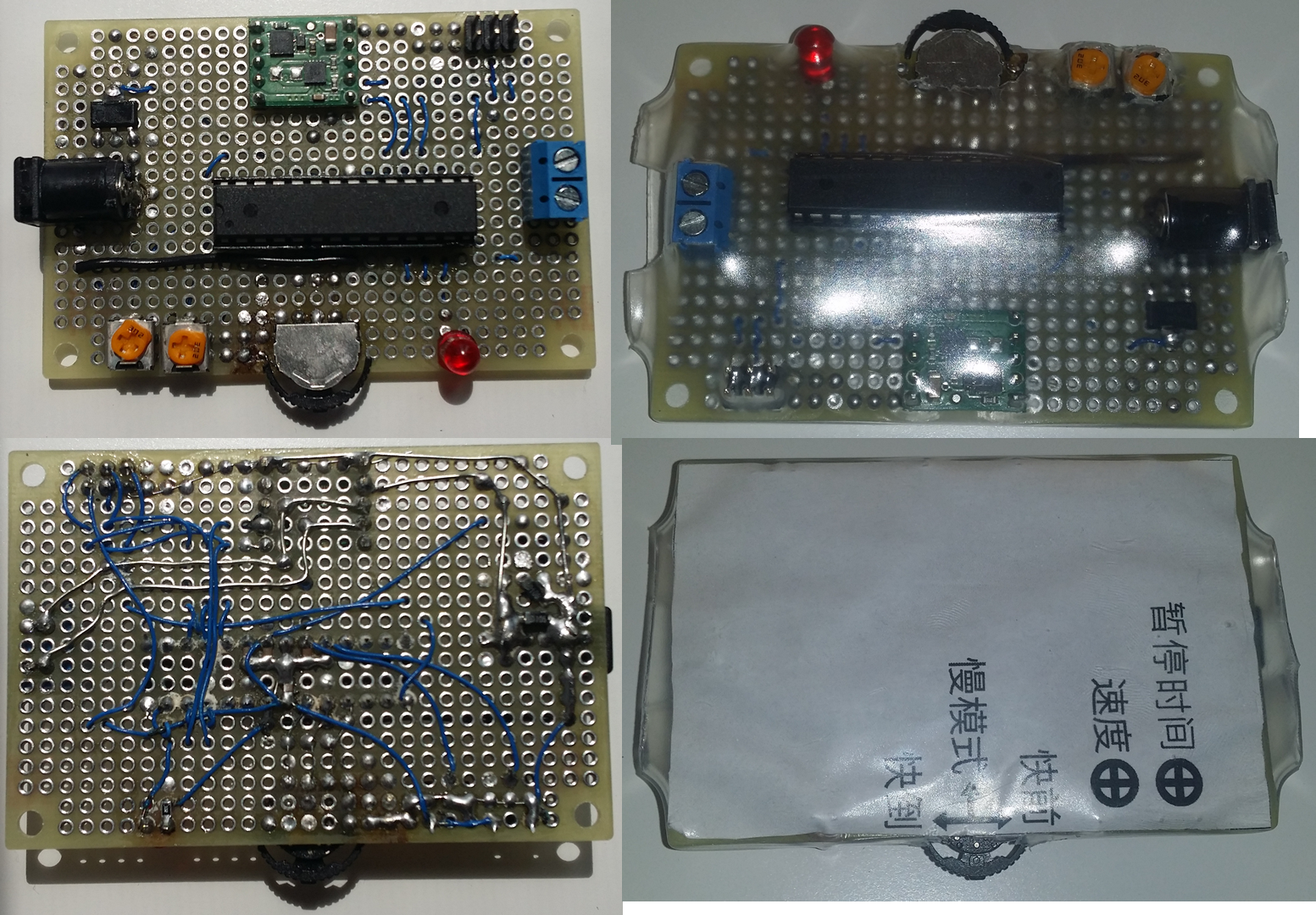
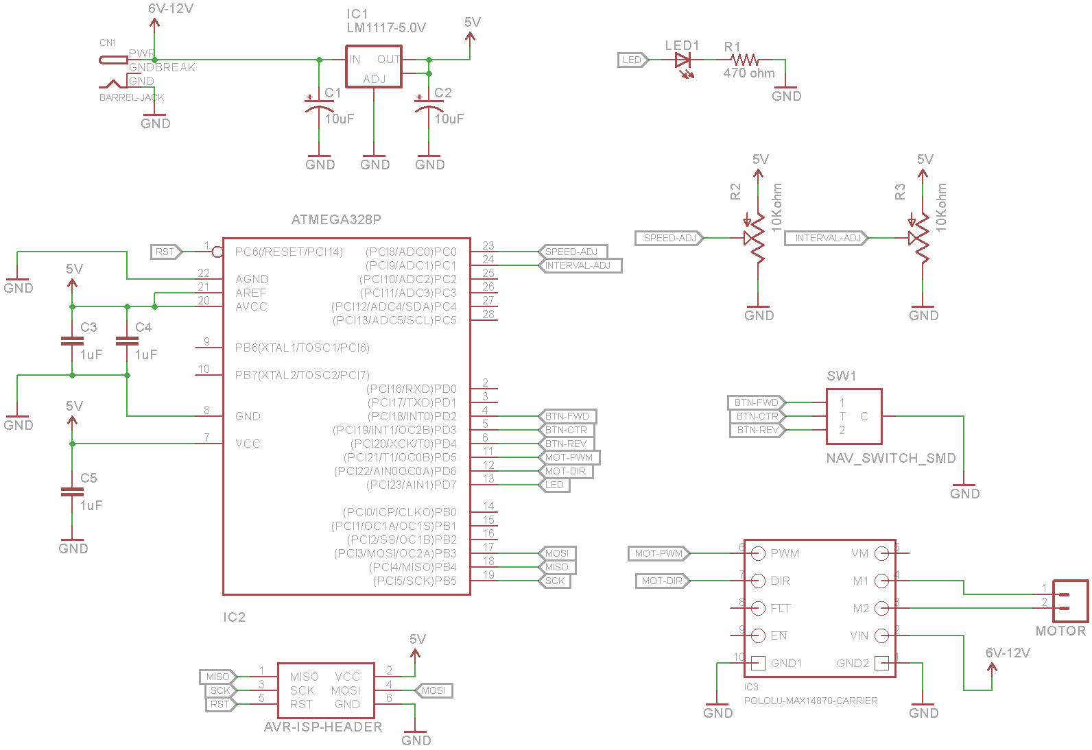
I made the circuit “doing it live”, as in, it was not pre-planned, except I purchased a H-bridge motor drive from Pololu (a MAX14870 carrier board), and dug out a navigation switch (with forward, reverse, center click) to use as the user interface. The MCU is a ATmega328P because who doesn’t have a couple of these? Power supply is an ordinary 12V wall-wart capable of 3A. LM1117-5 is used as the 5V voltage regulator to bring the 12V down to 5V to power the MCU. Everything is soldered onto a small perfboard. All passive components are 0805 SMD sized. Wiring is done using 30 gauge kynar coated wire. Finally, it is wrapped in super wide clear heat-shrink tubing, along with a piece of paper (with instructions printed on). With my skills and experience, I can design, solder, and program a simple project like this in a day.
Firmware is written as just one C file, here. You can open it with Atmel Studio.
Sooooo… sorry, no PCB files. But here is the circuit diagram that I drew after I finished the circuit:
FAQ Q & A
- Why not just buy one off the shelf
- All the ones in China are absolute garbage in terms of quality
- Need to make sure it meets the specs, must be capable of thick liquids, and speed control
- Price for a scientific or medical pump is extremely high
- A lot of them are precision pumps with stepper motors, which require additional complexity in the circuit and doesn’t have as much torque as a geared DC motor
- Engineering practice for me
- There are a few designs of peristaltic pumps on Thingiverse, why didn’t you just use those?
- Vague or hard to obtain parts, inadequate specifications, some of them don’t even use bearings, one of them require you to take apart a computer fan to use as a motor. This isn’t a scrapyard challenge…
- I will always design my own things whenever I feel confident, and I always feel confident. I didn’t buy a 3D printer just to print stuff off some search engine. Do you honestly print pictures off Google search results using an inkjet printer?
- I’ve seen much simpler designs without an outer casing, why does yours have one?
- Those designs work for liquids, the tube will get flattened from the stretching. But I wanted mine to last longer, by having less stretching, and more compression, allowing for higher pressures with thicker fluids.
- How did you determine the sizes of everything?
- Check for easily obtainable parts
- Estimate flow using cross-sectional area of the tube and the circumference of the pump
- Check recommended bend radius of tubing
- I took a sample of a feeding tube for reference
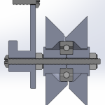
- Obviously model everything in CAD to check for fit first
- Adjust for shrinkage after test print
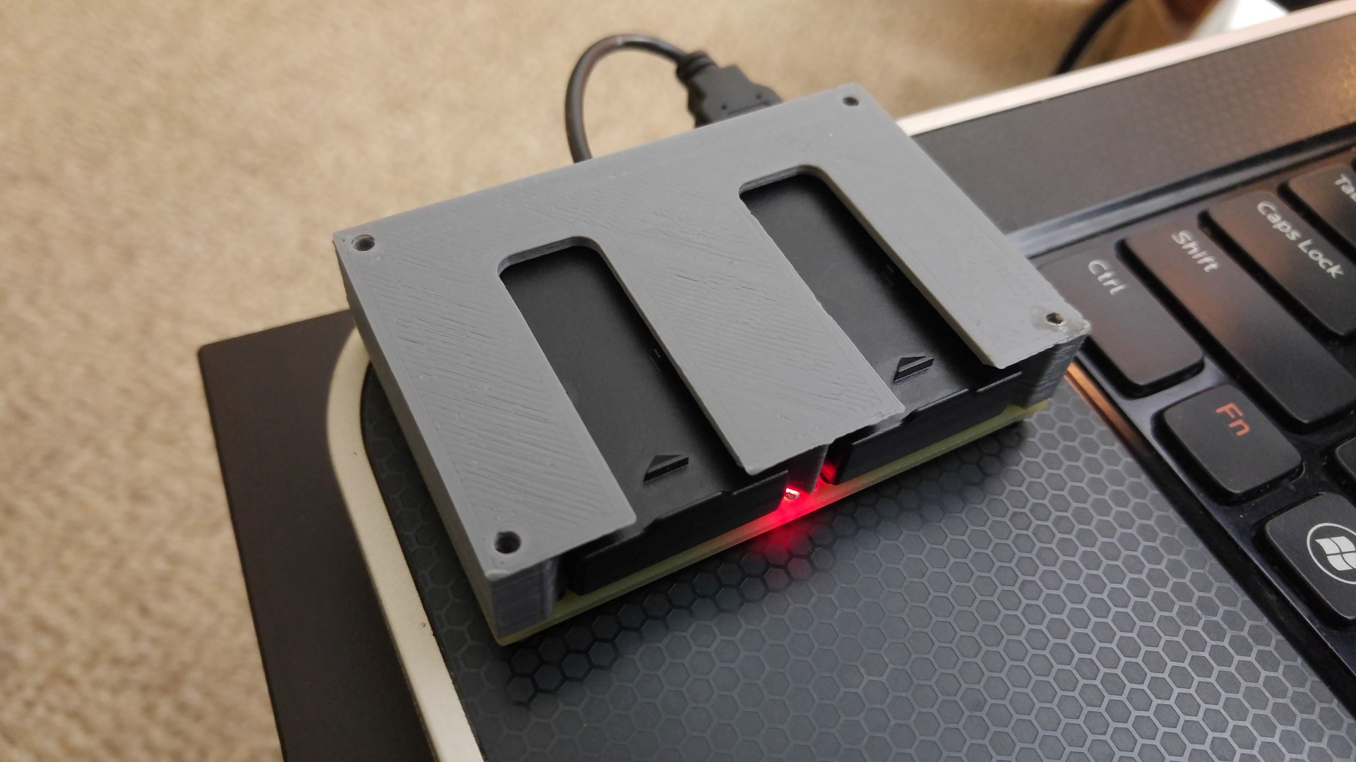
- Why does your workmanship look so rough?
- Shrinkage, because I used 100% infill on a really thick design
- My 3D printer suffered a key component failure, I wasn’t able to re-print.
- I don’t own a saw or drill press, everything had to be done free-hand
- I wanted it done fast, from me coming back from China, to shipping the finished item back, took exactly 2 weeks.
- Why didn’t you use a PCB?
- I have a large stock of small perfboards and 30 gauge kynar coated wire exactly for super fast 1 day projects, PCBs take a while to design and manufacture, and isn’t required for the parts I anticipated being used.
- What filament and what are the print settings?
- Generic PLA
- 210 degrees C nozzle, 60 degrees C bed temperature
- 0.1mm layer height but 0.2mm is acceptable if infill print speed is reduced
- 40mm/s shell speed, 120mm/s infill speed, 80mm/s everything else
- How long did it take to print?
- The case pieces take 30 hours, the rotor pieces take 6 hours
- PLA has a low glass temperature, are you not worried about it deforming?
- Before printing began, I did consider this, and concluded the following: The plastic is thick. I used bearings to reduce friction. The motor is extremely slow. The gearbox acts as a heat break.
- A long duration test showed no signs of anything getting hot.
- You told me about this project months ago, why am I just seeing it now?
- It was built and shipped in 2 weeks, shipping it fast was a priority. The documentation is secondary. The Onshape CAD files (which were completely re-drawn) and the schematic drawing were both done long after shipping.