


Upgrading an LC Meter Kit: A DIY Enhancement Project
Upgrade Your Budget LC Meter Kit: A DIY Enhancement Project The HU-053 LC Meter kit is a budget-friendly option for measuring capacitance, inductance, and frequency, available online. With its easy-to-solder components and transparent acrylic enclosure, it’s a great weekend project for electronics enthusiasts. But how accurate is it, and can we make it better? Kit Contents and Assembly The HU-053 kit includes a double-sided PCB, a bag of components, a transparent acrylic enclosure, and all the necessary nuts and bolts for assembly. The assembled device measures 91 × 106 mm with a height of 28 mm, featuring an alphanumeric LCD, a 40-pin STC89C52RC microcontroller, a 3P4T function selection switch, and a ZIF socket for connecting the component to be tested. The unit is powered by a 5-V supply. Improving the LC Meter’s Accuracy After assembling and testing the device, we were disappointed to find that its accuracy was as low as its price. But this presented an opportunity to improve it! In this article, we’ll explore ways to enhance the HU-053 LC Meter’s performance, making it a more reliable measurement instrument. Download the article to learn how to upgrade your budget LC Meter kit and turn it into a useful tool for your electronics projects.
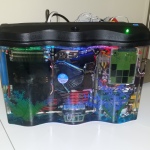
Aquarium Computer
My trusty laptop is showing its age. 8 GB of RAM is not enough for the amount of 3D stuff I do now, and it can’t run the latest games at all any more. Since I got a full time job now (instead of a constantly travelling student), it’s time to get a desktop PC (first PC build, yay). But the process of building a PC is pretty boring, it’s just an exercise of picking out compatible parts for the right price. I decided to make it slightly more interesting by submerging the entire computer in a fish tank full of mineral oil. UPDATE March 2015, I added a funny naked HDD activity indicator Some pictures from the build process Animated Loop Short Story (long story later, technical details and stuff): Intel i7 4790S, Nvidia GTX 970, H97M chipset, Corsair CX600M. Built onto a polycarbonate tray that is then dipped into a fish tank full of mineral oil. Fancy features like bubbling treasure chest, NeoPixel LED strip, oil pump+radiator, temperature monitoring, removable SSD. (part list? fine… here… these are not the prices I paid but here it is http://pcpartpicker.com/user/frank26080115/saved/HFDmP6) Comments and questions are welcome, I would love to chat with you! Reddit posts, please upvote: http://www.reddit.com/r/battlestations/comments/2pdd3q/aquarium_computer_mineral_oil_submerged_details/ and http://www.reddit.com/r/buildapc/comments/2pdeak/build_complete_aquarium_computer_mineral_oil/ Hi Hack a Day visitors, small correction: there’s 32 GB of RAM, I just didn’t put the same item twice in the part list. News/Updates will be posted at the bottom of this page…
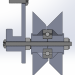
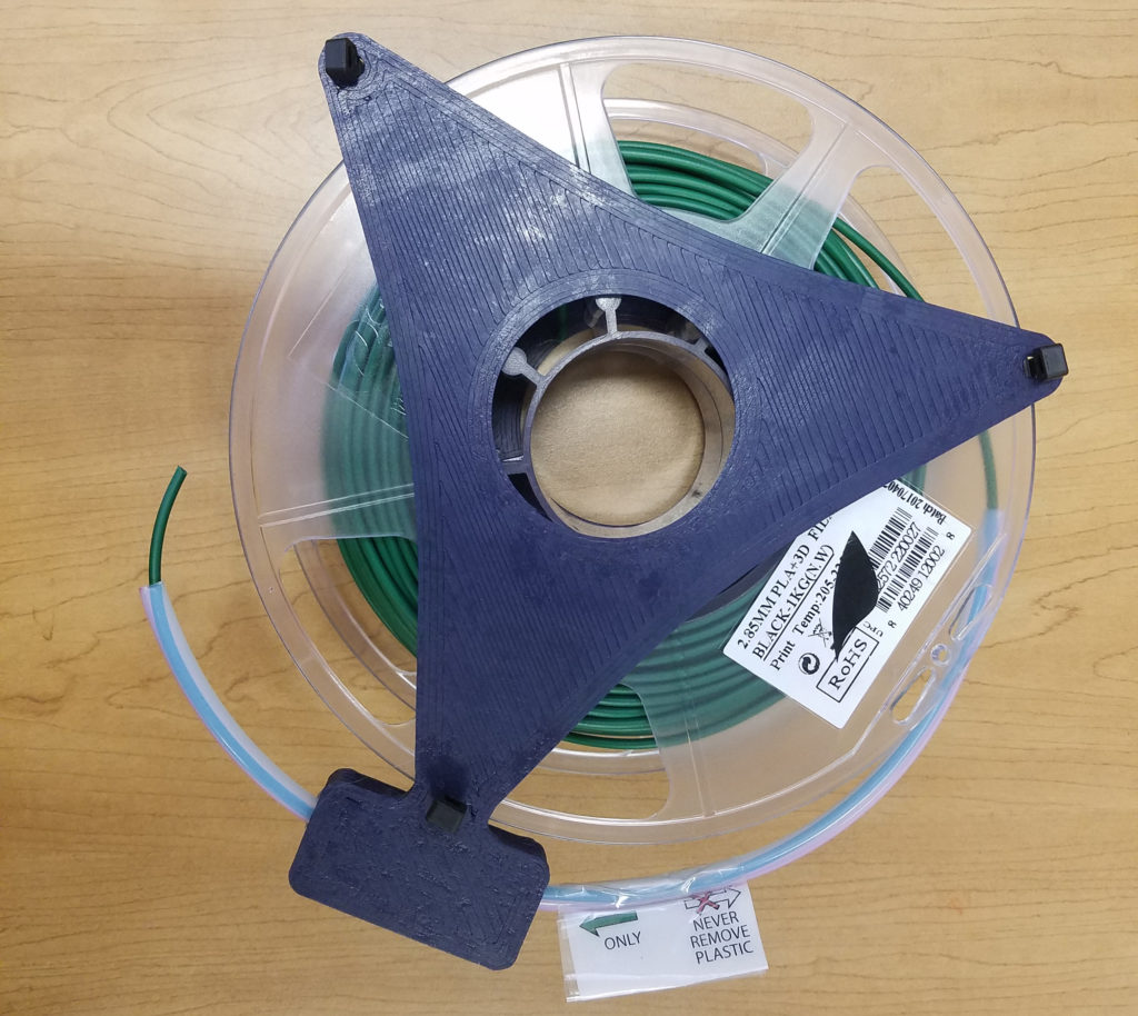
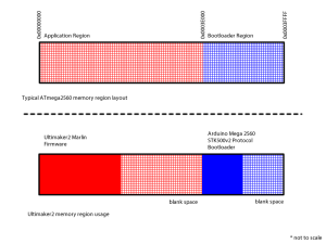
Ultimaker2 Bearing Spool and Bearing Guide Upgrade
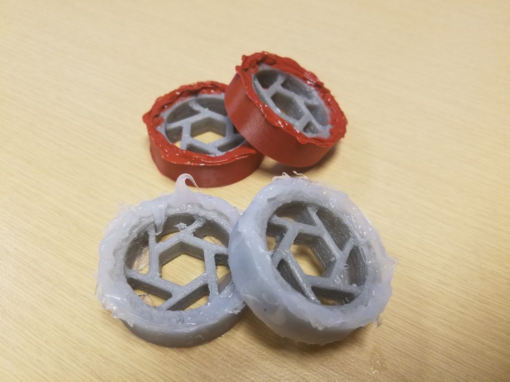
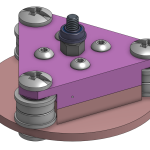
This is an upgrade to the Ultimaker2 3D printer for people who have spools that do not fit the original spool holder, and spools that are too tight and thus do not feed smoothly, causing under-extrusion. It is composed of two assemblies: a replacement for the filament guide and a replacement for the spool holder. Both utilizes ordinary skateboard bearings to achieve smooth rotation. The conical shape of the spool holder allows for any sized spool to be used, easily swapped because it uses a wing nut. Files are available on YouMagine. I want to emphasize that I am sharing the STEP files, not just STL, because STL are harder for people to import and modify than STEP files. SolidWorks files are also provided. The cross section images shows you how to assemble the upgrade parts. The screw diameters are #6 for the filament guide and 5/16″ for the spool holder. Please figure everything else out from the cross section images.
3D Printed Battery Recharge Dock for Parrot Rolling Spider
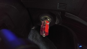
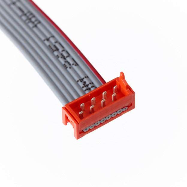
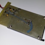
I got a Parrot Rolling Spider for fun. The batteries are 570mAH and the life is under 10 minutes, plus the reviews often mention that the batteries will lose their capacity quickly. Further research into this problem indicated that charging them slowly will alleviate this problem. I wanted a few spare batteries and a way to recharge them. I decided to DIY a dock for them. I had a handful of spare parts, such as the MCP73831 and plenty of small perfboards. All I needed to do was 3D print something to hold the batteries in place, and this is what I came up with. More pictures if you continue reading. The red LED is always on as long as there is power. When a battery is done recharging, a green LED will turn on. The MCP73831 are configured to charge at a slow 200mA each, totalling 400mA, which is under the 500mA limit for low power USB ports. Sure… I could’ve probably fit 6 batteries onto one board, standing vertically. But I didn’t want to actually buy 6 batteries for a toy. Sorry, no circuit diagram was drawn prior to the rapid prototype, but it’s nearly identical to the example circuit inside the MCP73812 datasheet. The battery connector is a 2199011-1 from TE Connectivity, or A120576 on Digi-Key. The design is shared on Onshape, click here. Print at around 27% infill and 1.2mm wall thickness. The…
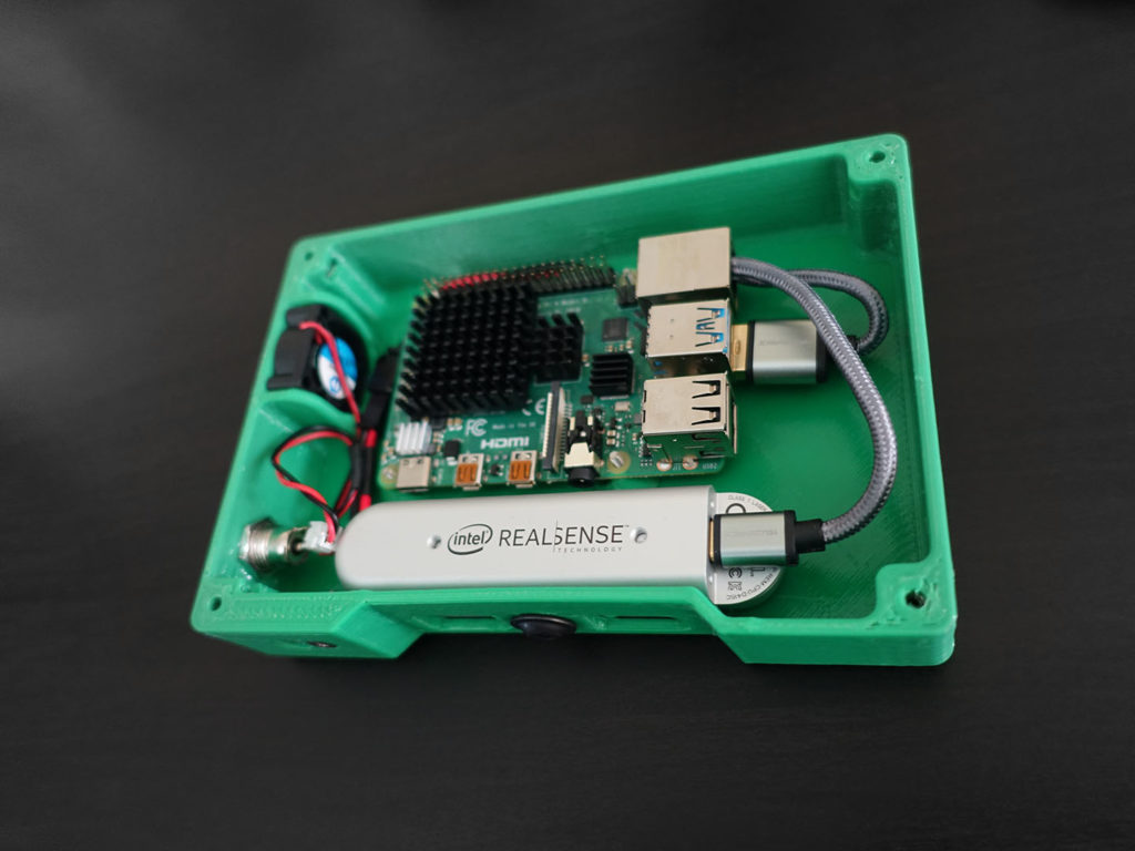
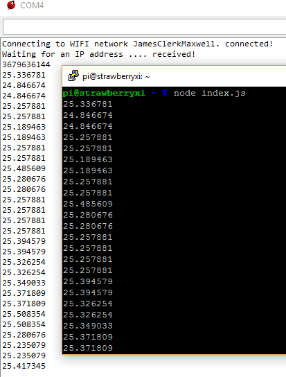
Using a Laptop as a Monitor for a Headless Raspberry Pi
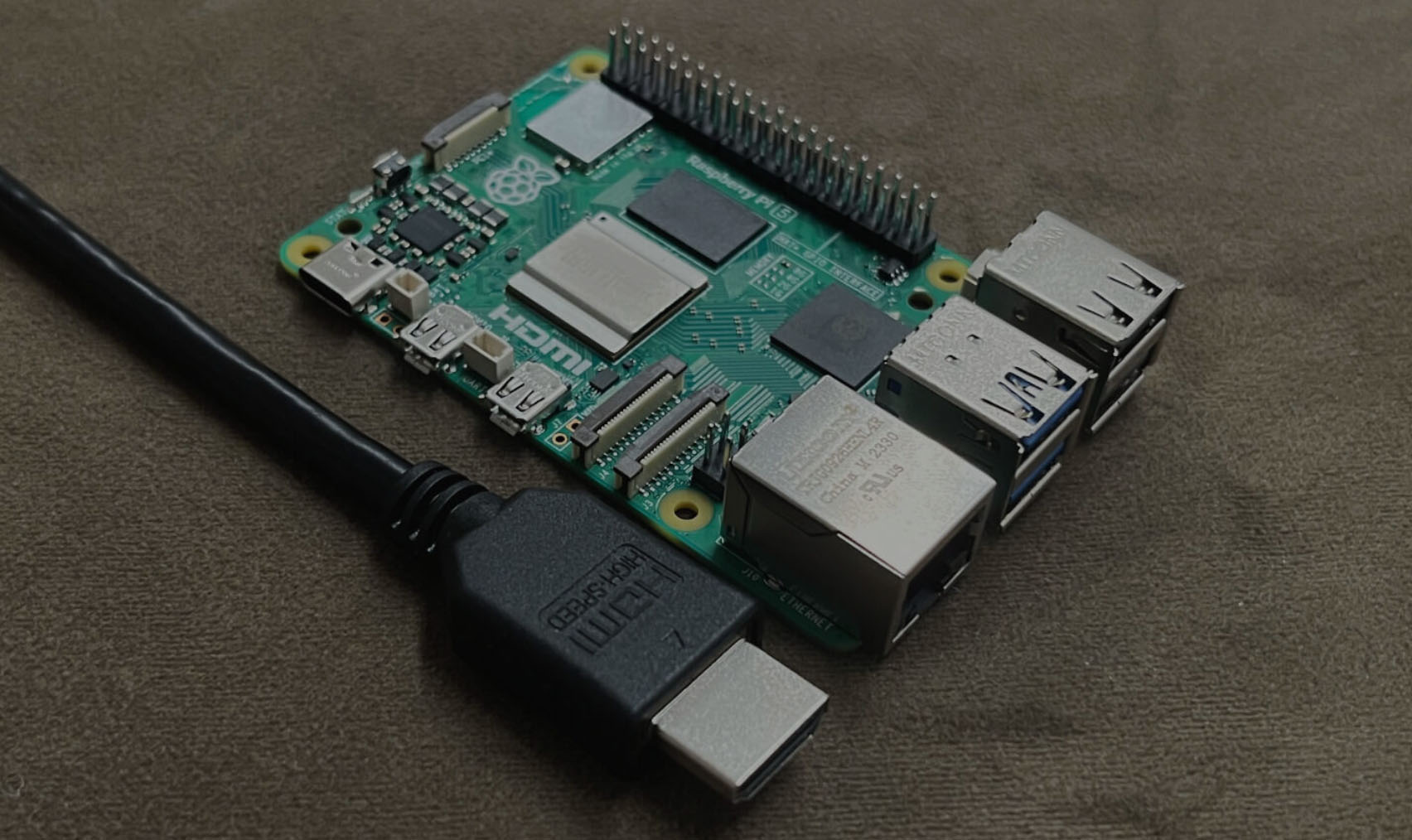
You’ve got a shiny new Single Board Computer, like a Raspberry Pi, for a headless project, but then you’re hit with the realization – no monitor in sight for the initial setup. Fear not, though, if you’ve got a laptop nearby, there’s a potential workaround waiting for you (and me). What are SBCs? On a single, compact circuit board, Single Board Computers (SBCs) pack a punch, integrating all the vital components of a computer. This includes a processor, memory, storage (via microSD cards or eMMC), and a range of input/output interfaces (such as USB ports, LAN, HDMI, and GPIO pins), along with power management circuitry. Their small size, affordability, and versatility make SBCs a go-to solution for a wide range of applications. There are some key points of why you would like to use an SBC: Some well-known examples of single-board computers include the Raspberry Pi series, Arduino boards, BeagleBone, and Odroid, among others. Each of these SBCs may have its own unique specifications and capabilities, catering to different user needs and project requirements. What kind of connection most SBCs have? Single-board computers (SBCs) typically feature different kind of connection options to facilitate their use in various applications. These connections can vary depending on the specific SBC model, but here are some of the most common types of connections found on many SBCs: It’s important to note that the availability and types of connections can vary…
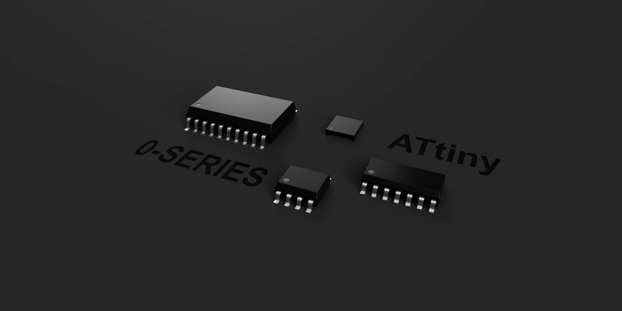
Introduction to tinyAVR Microcontroller Attiny404 Architecture, Features, and Related Registers with a Simple Code Example
In this continuation of the tinyAVR tutorial series, this blog post delves into the AVR CPU architecture, capabilities, and registers. Table of Contents Features Overview AVR is a well known 8-bit CPU. The CPU is a heart of the device which can access memories, do calculations, execute instructions, control peripherals as well handle interrupt routines. Most part of this post is based on the official Attiny404 documentation, so for in-depth info check the datasheet. Architecture AVR CPU uses a Harvard architecture with separate buses for program and data. While one instruction is being executed by the CPU, the second is being fetched from the program memory – this pipeline allows instructions to be executed on each clock cycle. As you can see in the image above, the CPU has ALU – Arithmetic Logic Unit. It can do logic and/or arithmetic operations between two registers or a constant value and a register. Also, ALU can execute single-register operations. When the ALU finishes an arithmetic operation, the STATUS register gets updated with the information about the operation end result. The ALU can directly access to a register file which consists of 32 8-bit general purpose working registers. All these registers have single clock cycle access time. To sum up, this allows single cycle arithmetic operations between two registers. Memory overview The program memory bus is directly connected to Flash, the addresses start from 0x0000. Whole data memory space is…
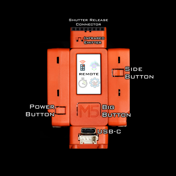
Wireless Camera Controller:Alpha-Fairy
I made(*) this tiny remote control for Sony Alpha cameras. Preface This is an open source firmware project. I wrote the source code for this project in Arduino flavored C++ and I am sharing it on GitHub. (*)I did not design the hardware nor do I offer it for sale. GitHub project main page Instructions for building and usage Features Minor Features Full Menu Map: The Story and the Challenge A while ago I owned a camera that was before bird tracking auto-focus was a well implemented feature, but got super envious when the Sony A1 was released. I ended up adding bird tracking to the camera myself, using a Google Coral to accelerate a simple pretrained neural network to point out birds and move the focusing point around on the camera. That project involved some reverse engineering of the Picture Transfer Protocol (aka. PTP) that is used by Sony between their camera and their PC app. Then I got interested in macro photography. There’s a technique in macro photography called Focus Stacking that I wanted to use but it’s a bit of a pain, some other camera brands offer this features in-camera, but not Sony. Knowing that it can be implemented with some commands over PTP, I wanted to add this feature to the camera as an external accessory. But this time it had to be a tiny battery powered wireless device. Here’s a demo video of Alpha Fairy doing focus…

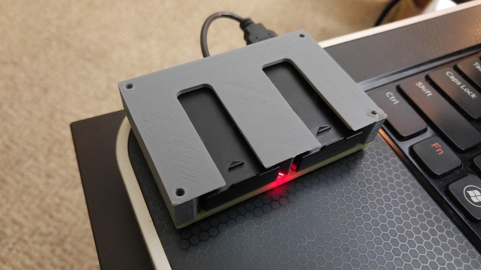
Toaster Oven Conversion: A DIY Reflow Soldering Solution
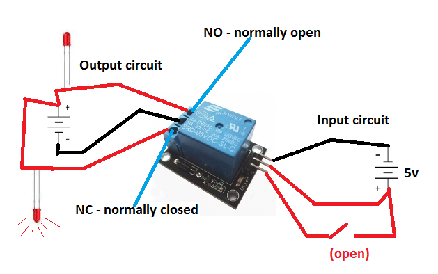
As I get more serious into my electronics hobby, I need to work with more SMD components. Some component packages are very difficult or impossible to solder with a traditional soldering iron. To solve this problem, I decided to hack a toaster oven to become a reflow soldering oven. Basically, to perform reflow soldering, solder paste is placed on a printed circuit board, and the components to be soldered is placed on top of the solder paste. When the oven heats the solder paste past the melting temperature, the solder paste melts and solders the component to the circuit board. To control the oven’s temperature, I created my own reflow toaster oven controller circuit. This circuit uses an ATmega32U4 microcontroller to monitor the oven’s temperature using a thermocouple and AD595AQ, and then control the oven’s heating element using a solid state relay. The controller features USB logging/debugging, USB bootloading, a graphic LCD display, and 3 buttons. The firmware features tweaking for all settings, manual temperature control, manual heating element control, and automatic temperature profile control (with a nice temperature history graph display). This circuit will plug into a wall outlet, and the oven will plug into this circuit, while the solid state relay basically acts as a switch between the wall outlet and the oven’s heating element. Safety is the main design objective (but some things were limited by cost), and ease of use is the…
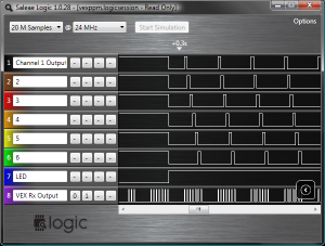
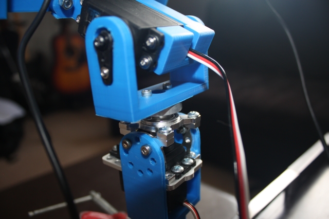
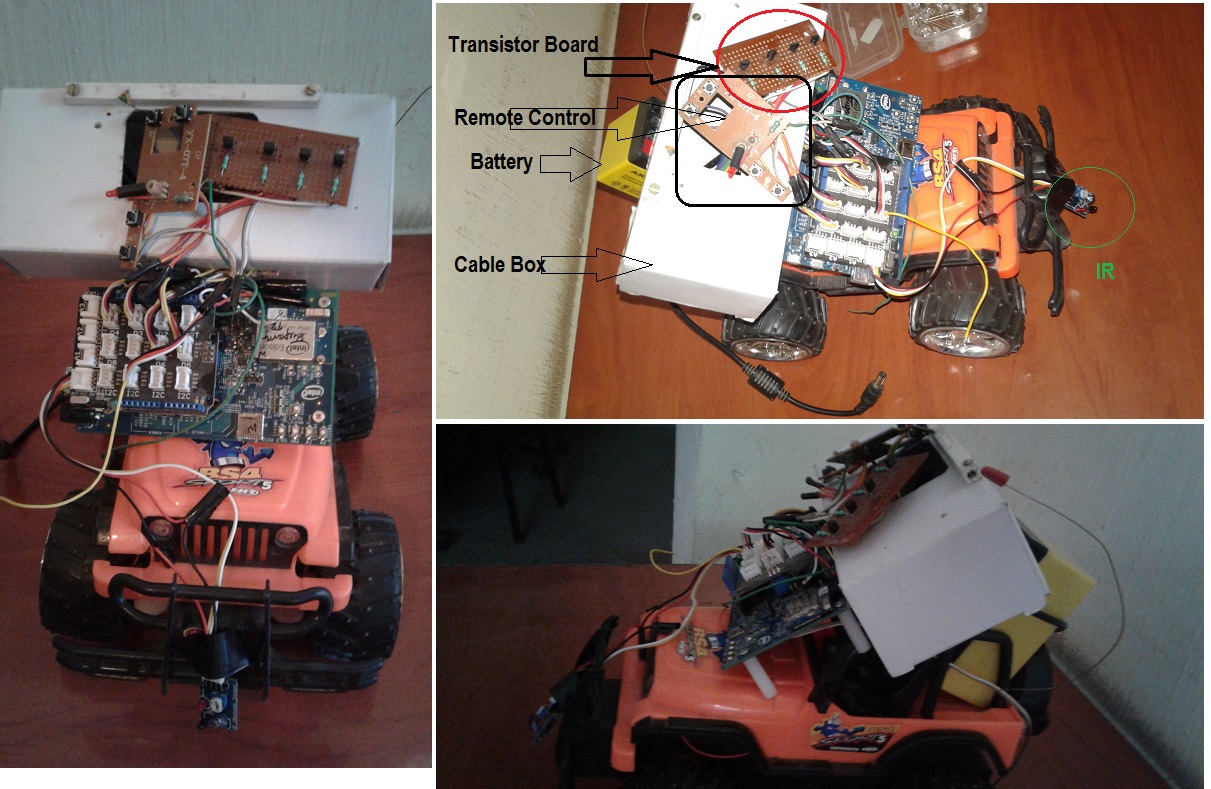
VEX Pulse Position Modulation Wireless Signal Decoder
1 Reply This is a PPM signal splitter for use with the VEX radio transmitter/receiver kit sold at All Electronics (item is now gone from their web site, this article itself is extremely old and outdated because newer technology has arrived) For $30 at All Electronics, you can buy a 6 channel radio transmitter and receiver. The transmitter is excellent for $30, trim, scaling, mixing are all programmable on the transmitter itself and it stores several configurations. The receiver only has one output pin, which outputs a PPM signal which needs to be split into individual channels in order to be able to control servos. If you put the receiver right side up and with the socket facing you, the pin on the far left is the Vdd pin, connect this to a regulated 5 volt power supply, the middle left pin is the PPM output pin (it is open collector so a pull up resistor is needed), and the middle right pin is the Vss pin, connect this to your circuit’s ground, the far right pin is not connected to anything inside the receiver. The 6 channel PPM signal has 7 periods of high and low pulses, each of these pulses all start with a high period of 500 microseconds, and a low period of varying lengths. The first low period is a sync pulse with a fixed low period of about 7 milliseconds, this…